In early 2012 an intriguing single-board computer with a weird name hit the market. For the low price of $35, you could get a fully functioning computer that could run a real operating system.
It was called the Raspberry Pi and it was the brainchild of a UK charity called the Raspberry Pi Foundation. They saw the need for an affordable computer after seeing a consistent drop in students applying to study computer science.
Well it turns out this tiny and cheap fully-functional computer had a much larger audience than anticipated. Multiple models have been created since, including the $5 Pi Zero, and over 9 million Raspberry Pis have been sold.
This is a long post so I more than likely made some errors along the way. Feel free to let me know on Twitter, thanks!
Is this like an Arduino? No.
While I have been hearing about the Pi for years, I never really took a good look at it and mentally just wrote it off as some kind of Arduino development board for enthusiasts to hack on. I couldn’t have been more wrong.
The Arduino is an open-sourced microcontroller with I/O pins to control other electronics. The Pi on the other hand still has those I/O pins (GPIO) but also has a closed-source ARM System on a Chip (SoC). However, the Arduino is better suited at connecting to analog sensors out of the box whereas the Pi works best with serial interface sensors using I2C or SPI communication.
The fastest Arduino runs at 84MHz while the Pi 3 runs at 1.2GHz.
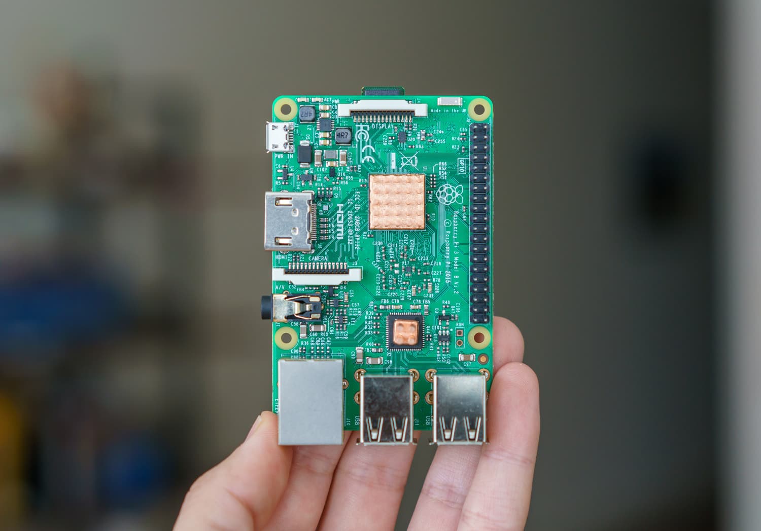
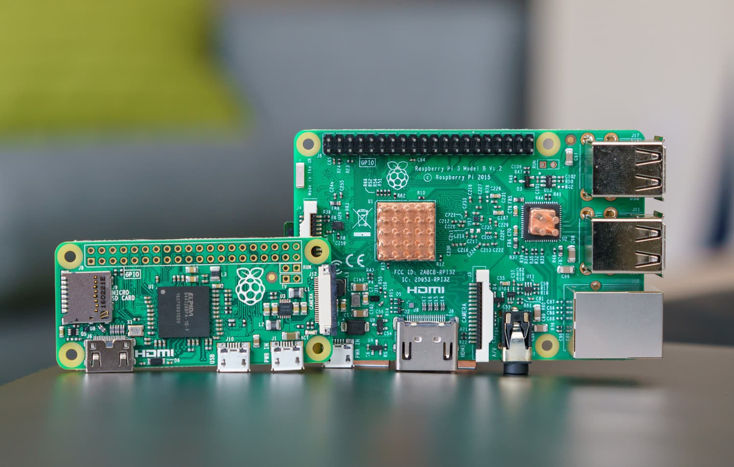
So what do I mean when I say the Pi is a fully-functional computer? Surely something that cheap can’t really be usable.. it is. Along with that 64-bit 1.2GHz quad-core CPU the Model 3 B features 1GB of RAM, 802.11n Wi-Fi and Bluetooth along with a myriad of ports: 4x USB, HDMI, microSD and more. That allows it to run operating systems optimized for ARM chipsets, and there are quite a few these days:
- Ubuntu MATE
- Raspbian and Raspbian Lite (Debian optimized for Pi)
- OSMC and OpenELEC (media center OSes)
- Pidora (Fedora for Pi)
- Arch Linux ARM (Arch optimized for ARM computers)
- Chromium OS for Single Board Computers (You might know it as Chrome OS as used on Chromebooks)
- Windows 10 IoT Core (A Windows 10 variant made for Internet of Things uses)
- Coming soon: Official Android support from Google
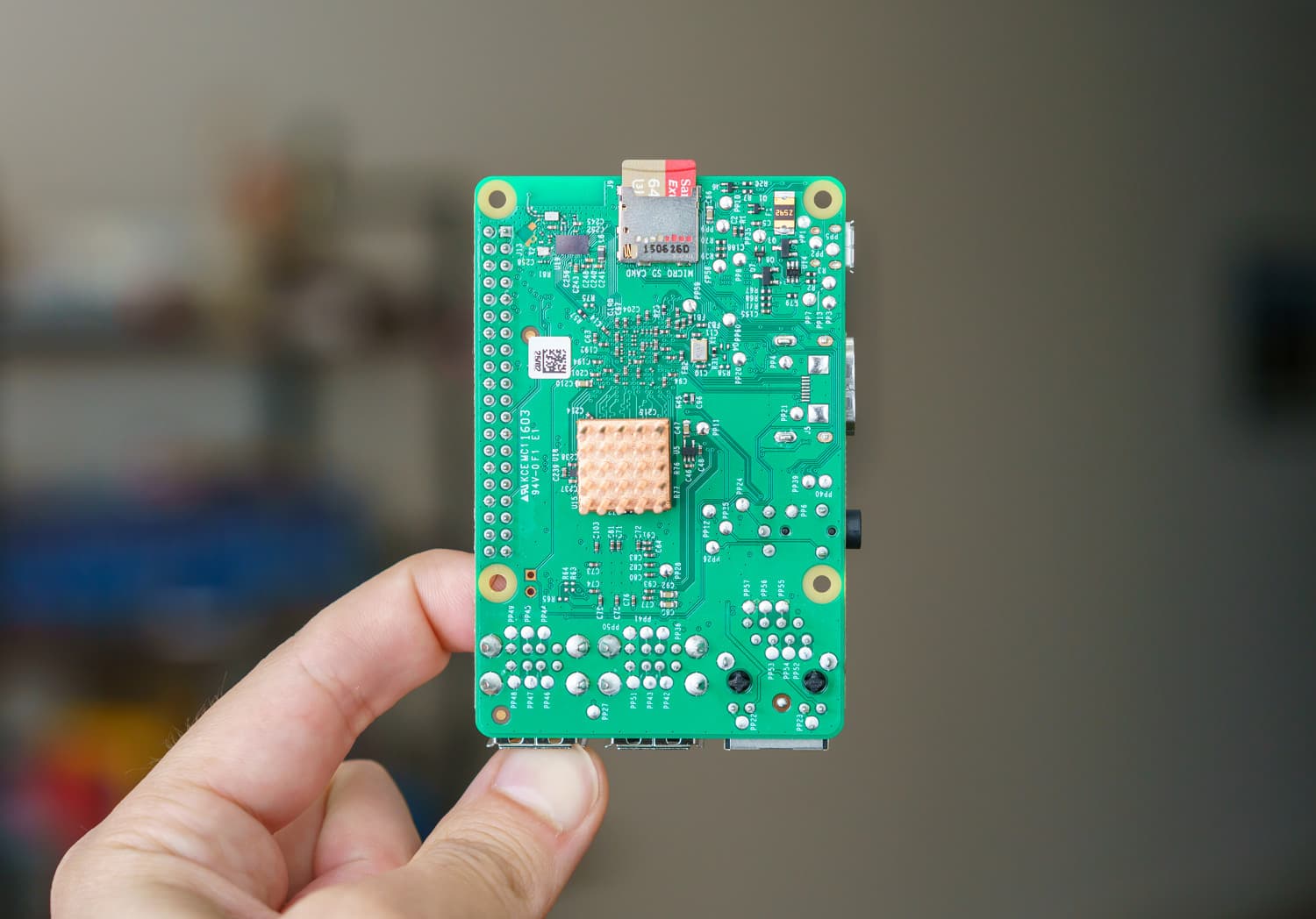
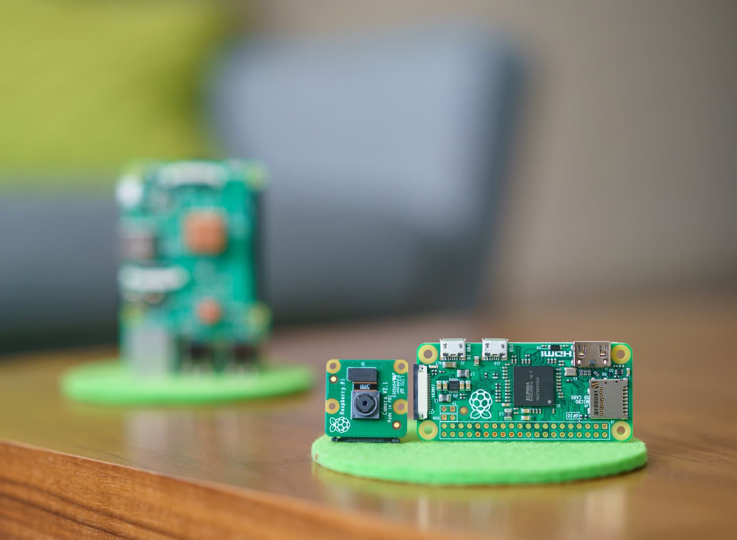
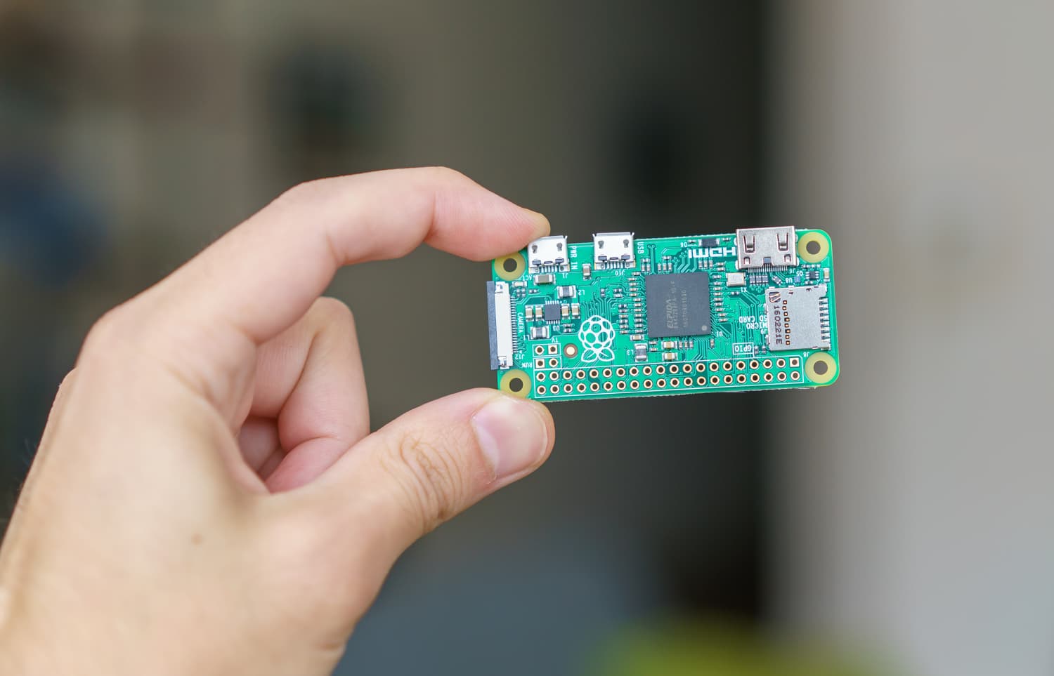
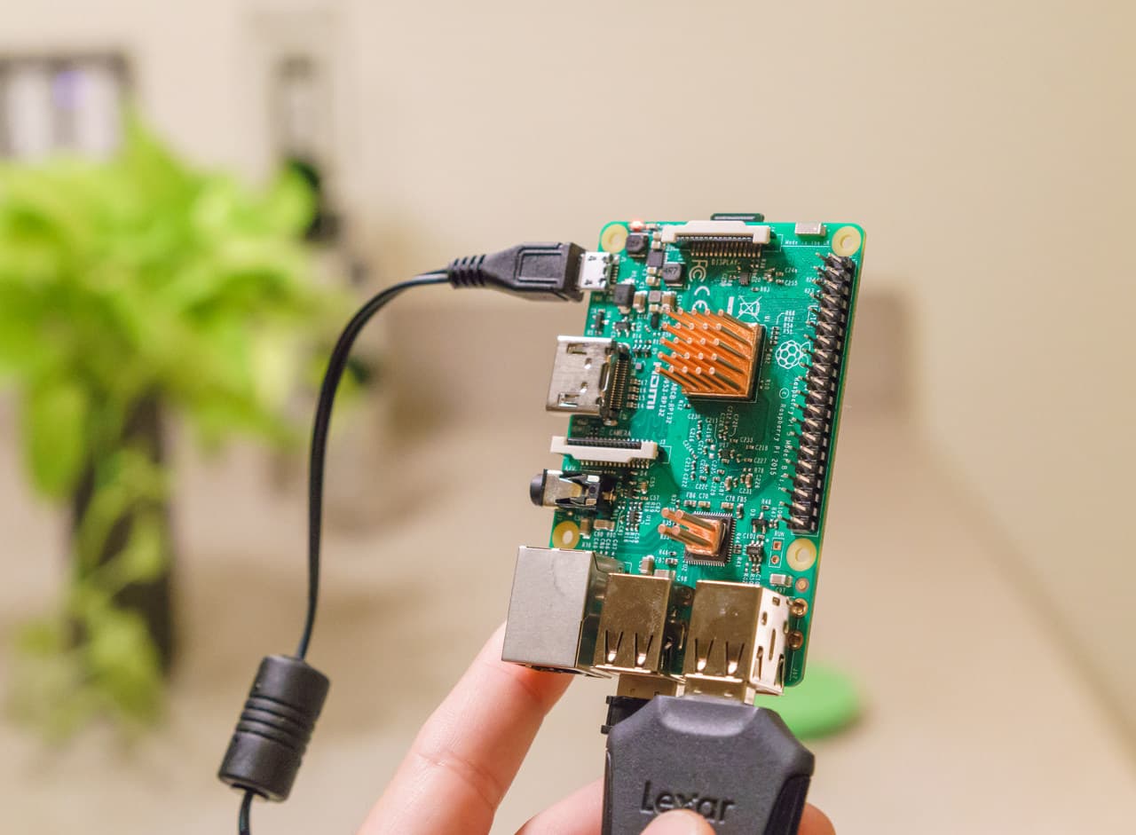
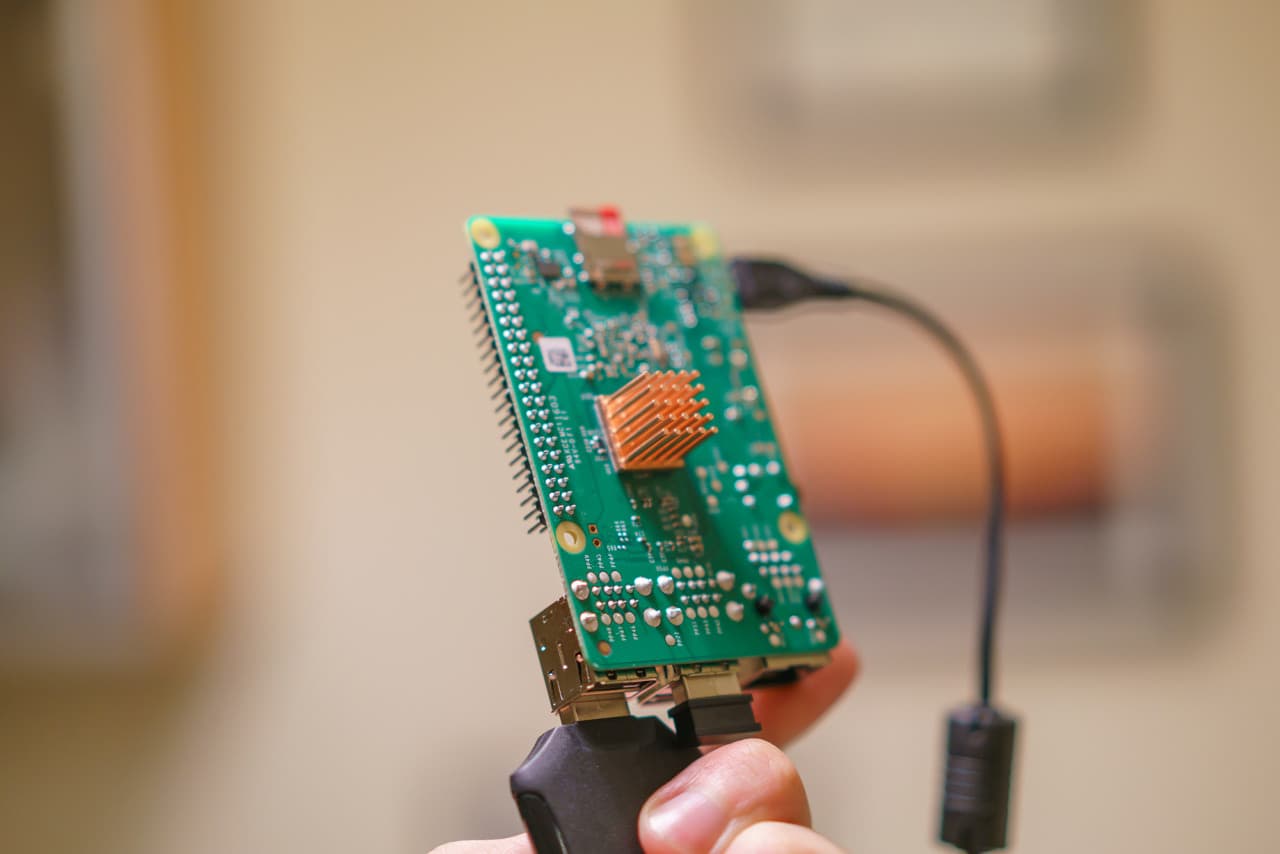
For comparison the smaller $5 Raspberry Pi Zero (v1.3 and camera module shown below) has a single-core 1GHz CPU and 512MB of RAM — still enough to run these operating systems too — along with its microSD slot, a mini HDMI and two micro USB ports. However, it lacks onboard networking and you'll need a USB dongle with USB Wi-Fi if you'd like Internet access.
There are lots of Raspberry Pi competitors. Some are more powerful and more expensive. There's the PINE64 with 2GB of RAM and Gigabit Ethernet, the 2GHz quad-core Odroid XU4 with USB 3.0 and Gigabit Ethernet as well as the blatant Raspberry Pi clone the Banana Pi1 with its SATA connection. However, nothing quite beats the Pi's massive developer and enthusiast community. This makes it easy to find support for projects you're building or use Pi-specific software projects.
Energy consumption
Oh and this thing sips electricity! Unlike larger computers where you may need to think twice about running it 24/7, Raspberry Pis cost almost nothing to run. This makes the Pi remarkably attractive as an always-on linux server or base for your connected hardware projects.
Consumption depends on the model and there are ways to reduce consumption even further2, but a Pi 3 Model B will draw around 1.4W at idle and up to 3.7W at load.
In the state of California where electricity costs around 15 cents per kWh, running a Pi 3 at load for a full year would cost just $5 (and just $2 per year at idle). A Pi Zero will cost signicantly less as it runs closer to 0.7W at load. For comparison, my 4 disk Synology NAS probably costs around $3.5 per month to run.
The diminuitive Pi power needs opens the door for interesting mobile and embedded uses as it can be powered by a normal USB battery pack for a good while.
Pi for education
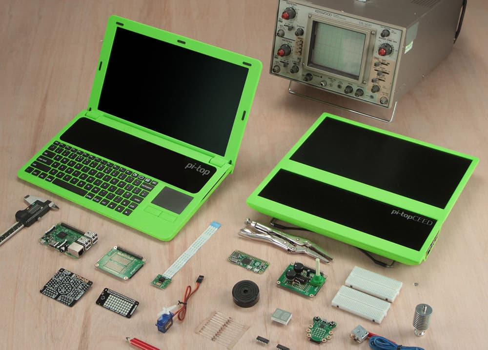
Before it became insanely popular with developers and hobbyists, the Pi was intended to be an affordable computer for education. That effort still goes on with the Raspberry Pi foundation trying to get Pis into schools and now there are new efforts like the Kano computer kit and the Pi-Top, both the result of successful crowdfunding campaigns.

Given these roots, there is quite a bit of education oriented software out there for the Pi: Sonic Pi for music, Scratch, Processing and Python, Minecraft Pi and much more. Sure, a lot of this can be done with any computer but the price point of the Pi makes it even more accessible.
Pi community and resources
Once you've decided to start tinkering around with a Raspberry Pi, you'll be happy to know you're not alone. There's a large community of Pi hackers to help you ideate, build and debug your projects, along with an abundance of Pi-specific hardware to bootstrap your projects.
- Raspberry Pi subreddit
- Raspberry Pi forums
- MagPi Magazine
- Raspberry Pi eLinux wiki
- adafruit - an online electronics store with a blog featuring lots of Pi news and tutorials
- Pi troubleshooting guide
What can you do with a Pi?
So much.
Why did I get a Pi?
I became Pi-curious after I had seen a friend using a Raspberry Pi Zero to control his Sonos setup with his Amazon Echo. Given that I have a Sonos system I wanted to set up the same to start. While I could easily just host the necessary node server on my NAS, I would prefer to keep that box invisible behind my router for security. I had no qualms forwarding ports for a simple Pi-based server.
I ordered a Pi 3 Model B that week and setup my own Sonos/Echo integration — while I had originally wanted the tiny Pi Zero, it was sold out everywhere at the time.
Alexa controlling my Sonos now. via Raspberry Pi via AWS lambda via Alexa Skills Kit 😂😍👌 pic.twitter.com/gsAEaZwSGD
— Paul Stamatiou (@Stammy) May 16, 2016
Then I started thinking about what else could be done with a Pi...
So what can you do with it?
There's the first and most obvious route: use it as a computer. It definitely won't be the fastest machine in your house but it can accomplish basic tasks well. While you can hook it up to a full size mouse, keyboard and desktop display, there are tons of options for smaller displays, including touch screens, that make the Pi ideal for various projects.
But remember how it has all those I/O pins? There are infinite hardware hacking and internet of things ideas that can easily come to life with the Pi at the center:
-
Digital photo frame
Digital photo frames are nothing new; you probably remember the crappy versions years ago where you stuck an SD card in to play your photos. Well times have changed and tons of connected digital photo frames are on the market now. There's the $299 Electric Objects EO1, the $999+ Klio and the $445+ Meural digital canvas. So now lots of folks have turned to the Pi to build their own versions, including me (at the very bottom of this post!).

-
Smart/Magic Mirror
Smart mirrors are probably the most popular Raspberry Pi project in existence right now. They bring memories of futuristic movie interfaces and are relatively simple to build, especially with a large community developing them and releasing software to drive them. In a nutshell: put a display running a full-page browser with a dark UI displaying info like news, weather or whatever is important to you behind a 2-way mirror and hang it in your house somewhere. There are lots of guides about this online: 1, 2, 3, 4, 5.


Probably the most popular magic mirror build. This one was done with a Fire TV Android stick since the creator couldn't find a Pi Zero in stock at the time. Same concept though.
-
Roll your own motion detecting Dropcam with motionEyeOS
-
Create an alarm clock that plays music from Spotify
-
Setup your own VPN server with PiVPN (OpenVPN) for when you're not at home and connect to unsecure coffee shop Wi-Fi networks.
-
Build your own portable Pi Desktop computer or tablet:


-
Build a document scanner that automatically uploads to Dropbox
-
Home theater PC with OpenElec, OSMC, Kodi, RasPlex or even Android TV (see video)
-
Create an "Onion Pi" Tor proxy
-
Setup an Ad blocker for your whole network with Pi Hole
-
Program your own Pi-based robot with the GoPiGo robot kit:

-
Make a personal voice assistant
-
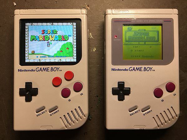
Make a portable gaming console, Porta Pi Arcade system or Game Boy Zero using with RetroPie.


-
Turn your Raspberry Pi into a gaming console with the Lakka Linux distro
-
Have your Pi run a Twitter bot that tweets photos from the Pi Camera
-
DIY Pi-controlled espresso machine using iSPRESSO
-
DIY Amazon Echo using Alexa voice service:

-
Setup wireless electrical outlets via RF modules made for the Pi or hack your own voice-controlled electrical outlets:

-
Update Jan 2017: Tim from the link above wrote another article on the topic, but this time around using the Amazon Echo to Control Wireless Power Outlets with your Pi
-
Create your own BitTorrent downloading box
-
Make a Raspberry Pi server cluster:

-
Have the Raspberry Pi open the door with a Slack chat command
-
Use it as a server for Home Assistant or pimatic for all the connected devices and appliances in your home or have it run HomeBridge to allow Siri to control more home automation devices.
-
Use your Pi to host any of these free web applications yourself
-
DIY Seenote digital sticky note / to-do list
-
Write a Python web server to control electronics connected to the Pi's GPIO pins from any browser
-
Play a MIDI file over a Tesla coil
-
Create a high-res networked outdoor camera:

What is the Pi not so well suited for?
For one, the Pi is a full computer and while it does not consume much power for a computer, it can still be overkill compared to an Arduino for simple hardware projects that don't require running an OS, GUI or networking.
The Pi is not without a few tradeoffs. Ethernet networking (which is a 100Mbps link) and disk access (if you attach any storage device via USB) all go through the USB bus. So any simultaneous Ethernet network traffic and storage device usage will be bottlenecked by the same bus. Wi-Fi does not route through the USB bus, but you will still typically only see around 20-40Mbps over Wi-Fi instead of the theoretical 150Mbps for 802.11n.
In short, the Pi is not quite the best for intense I/O and networking uses but can get the job done when speed is not mission critical.
Getting started
OS installation
What you need
Okay, let's get started! I'm going to assume that at the very least you'd like to just install some operating system on a Pi. First you'll need to pick what Raspberry Pi and accessories to buy — you didn't think you could get away with just buying the Pi itself did you?
But what Pi do you want? There's the larger and more powerful Pi 3 Model B and the tiny Pi Zero. I ended up getting both, but if the cost difference isn't a big issue for you I'd suggest starting with the Pi 3B. With integrated Wi-Fi as well as full-size HDMI and USB ports, it's almost a turn-key solution.
-
Raspberry Pi 3 Model B — $35
- Buy from: The Pi Hut, MCM, Adafruit, Pimoroni, Amazon
- The heart of your Pi projects. Unfortunately, Amazon themselves do not sell it (just third parties, often at a higher price) so it's probably best to purchase from one of the official partners above.
-
2.5A micro-USB power adapter — $10
- Just about any micro-USB power adapter should work, but the more power hungry devices you connect to your Pi the more critical a good power supply becomes. Lots of Raspberry Pi issues that crop up end up being caused by a bad power source, so it's best not to mess around and get a good one. While I have a ton of USB chargers already, I opted not to get a powerful one used by many Pi folks without issue. Another option is this Anker Dual USB charger with 2 2.4A USB ports if you have other devices to run simultaneously, which I also ended up purchasing later on for my Pi Frame project below.
-
16GB microSD memory card — $10
- Anything larger than 8GB should be fine, but it's very important to get a fast card (Class 10 at least) from a reputable brand. Faulty or slow microSD cards are often a source of Raspberry Pi woes, so it's best not to skimp around in this department either.
- I already had a bunch of large and fast microSD cards from my GoPro, so I just used one: a 64GB SanDisk Extreme. If you want something even faster you can opt for the SanDisk Extreme Plus or SanDisk Extreme Pro version.
You'll also need a keyboard, mouse, HDMI cable and a monitor or TV3. I'm assuming you probably already have these lying around. A USB keyboard and mouse are ideal so there's no issues getting it to connect during initial setup. As for the display, you really only need it for the setup process. After that you can install a VNC server and access it from any computer (if your intended Pi use doesn't require a display all the time).
- Case for the Raspberry Pi 3 — $9
- There are a million to chose from so I encourage you to search around though to see what's out there.
- Tiny wireless keyboard/trackpad — $32
- While I have a full-size USB keyboard and mouse, I ended up getting this tiny keyboard mouse combo for casual usage. Easy to hide away when not in use.
What operating system?
There are lots of operating systems to choose from when it comes time to image your microSD card and start the installation process. The typical Raspberry Pi setup advice involves installing NOOBS which makes it easy to select between Raspbian, Pidora, OpenELEC, OSMC, RISC OS and Arch Linux. Most newcomers select the Debian-based Raspbian Jessie, the official operating system for the Raspberry Pi.
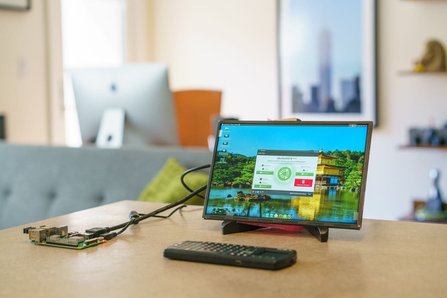
I used Raspbian for a bit but then Ubuntu MATE 16.04 optimized for the Pi 3 came out. I went with Ubuntu MATE largely for a superficial reason — I like how it looked out of the box.
There are a few downsides compared to Raspbian — hardware acceleration seems to be a bit experimental, so I would not suggest this OS if you plan on using it for any Home Theater PC needs. Also not every Ubuntu package is ARM processor friendly so you may find less applications you can use at the moment on Ubuntu MATE. Also Firefox is pretty slow on Ubuntu MATE so you'll want to install another browser like Midori (or Chromium once they solve their current crash issue).
Imaging the microSD card
This part is usually harder than it needs to be. Typically you would download the image and use a command line tool like dd to manually image the card. You can't just drag the file to the microSD card.
I ended up going the hard route with the command line to image my card with Ubuntu MATE, but I'll be listing an easier option below.
-
Download the Ubuntu MATE 16.04 LTS image made for the Raspberry Pi. You should get a file named
ubuntu-mate-16.04-desktop-armhf-raspberry-pi.img.xz. -
Uncompress the image. You can install the command line tool unxz or use a GUI app like The Unarchiver. I chose the latter:
unxz ubuntu-mate-16.04-desktop-armhf-raspberry-pi.img.xz -
Plug in your microSD card (you'll probably get an SD card adapter with any card you purchased) and run
diskutil list -
Identify the disk for your microSD card. This should be something like
/dev/disk4, not/dev/disk4s1(The "s" part denotes the partition and we want the whole disk). Triple-check that this is the correct device and size. You may want to eject it and put it back in and verify that the item is removed fromdiskutil listwhen you do this. You don't want to overwrite the wrong disk! -
If this disk is not listed as being FAT32, you will need to format it as DOS FAT32. You can do this in OS X by opening up Disk Utility, selecting the microSD card, clicking Erase and then selecting MS-DOS (FAT).
-
Unmount the disk, with the "X" being the number you just identified:
diskutil unmountDisk /dev/diskX -
Now we get to start the actual imaging process. Verify the name and location of the downloaded .img file you extracted, and enter in the correct disk location (the /dev/diskX part) and run this:
sudo dd bs=1M if=~/Desktop/ubuntu-mate-16.04-desktop-armhf-raspberry-pi.img of=/dev/diskX -
Alternatively you can try an even faster method by using the raw disk location instead of the buffered disk identifier. Just add an "r" before the disk like so: /dev/rdisk4. This may not work for everyone:
sudo dd bs=1M if=~/Desktop/ubuntu-mate-16.04-desktop-armhf-raspberry-pi.img of=/dev/rdiskX -
This will take a long time. For my 64GB card it took 48 minutes using the first approach (not the rdisk method). You get no status from the dd command while it's working but you can press CTRL+T to get an update.
-
When completed you can pull out the card and put it in your Raspberry Pi! If you have any questions about this process or are not using a Mac, there are lots of more detailed guides online like this one and this one.
If you're dying to just get started immediately you can buy a microSD card with NOOBS preinstalled or create your own and install Raspbian Jessie or another OS instead of Ubuntu MATE.
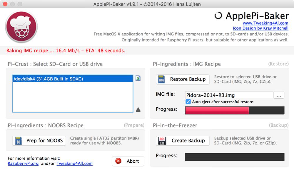
But there's an easier way for OS X users: a new tool called ApplePi-Baker. It's ridiculously easy to use. It automatically detected my microSD card and all I had to do was select the extracted img file. It did the rest and my card was ready to use after a few minutes.
Boot it up!
With your new SD card ready to go, slide it in your Raspberry Pi 3 and power it up. It should boot into the setup wizard for whichever OS you chose. This part should be a breeze. After a short while you'll be greeted with your new OS! Take some time to browse around and get it setup to your liking. But you'll first want to resize the file system. You'll find it in the Ubuntu MATE welcome dialog here:

Set a DHCP reservation
The majority of how I work with my Pi is actually over SSH and VNC rather than directly using it on a display. As such it's important that I can always find the Pi on my network at the same IP address. To do this I added a DHCP reservation with the AirPort Utility (I have an AirPort Extreme).
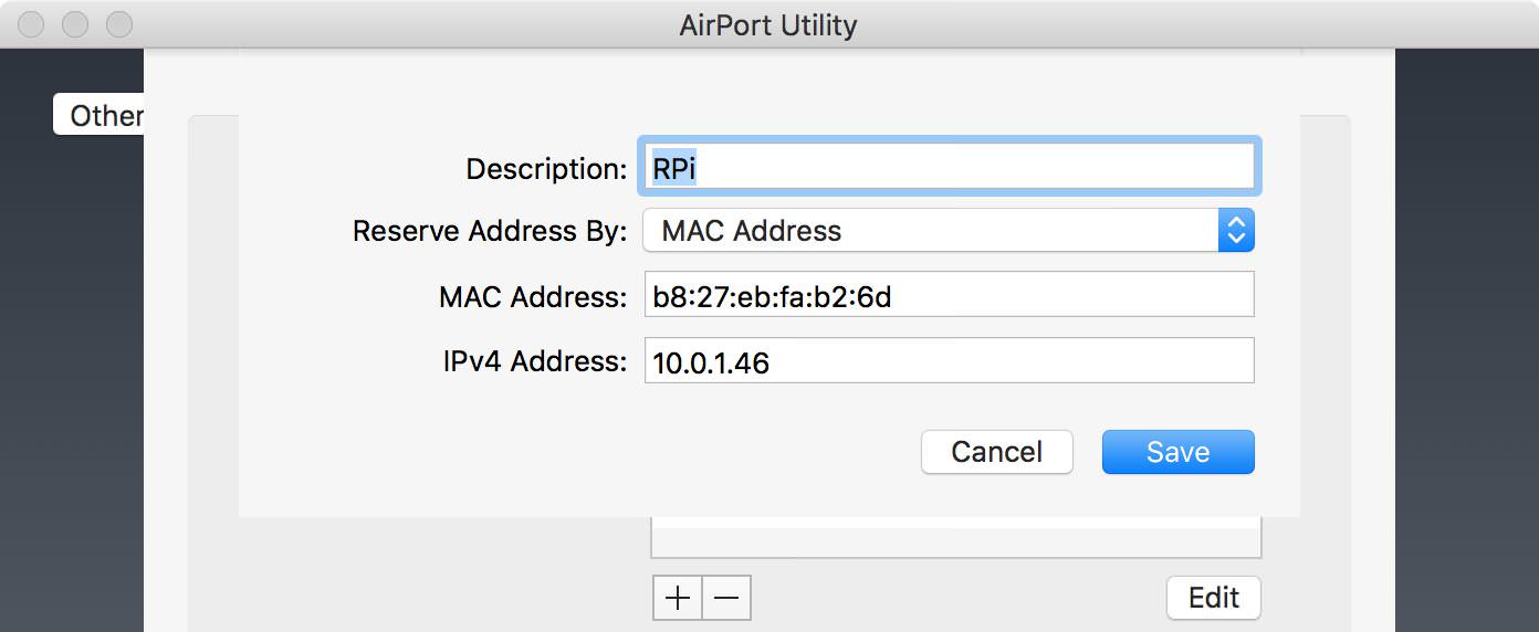
To do this you'll need to know the MAC address of your Raspberry Pi. You can do this by running ifconfig eth0 if you're connected via Ethernet, or ifconfig wlan if connected via Wi-Fi.
Now you can always ssh into your Pi from any computer on your network (or from any computer if you also setup port forwarding) with the same local IP. The default username for Raspbian is pi but you will have set your own username for Ubuntu MATE.
ssh pi@10.0.1.46
Setting up VNC
Unless you have a dedicated display for your Pi, it will probably be annoying to constantly have it plugged into your TV. Installing a VNC server on the Pi and a VNC client on another computer will let you see and control the Pi with the window manager GUI instead of via SSH command line.
While either SSH'd in or directly on your Pi, install the Tight VNC server:
sudo apt-get update
sudo apt-get install tightvncserver
tightvncserver
Now you need to enable the VNC server on the Pi. While it's sufficient to just type tightvncserver to run it, you'll want to customize a few things to get a higher resolution display, especially if you're accessing it on your LAN. Running the following command will setup a virtual screen with resolution of 1920x1080. You can use any screen resolution you like here within reason:
stammy@rpi:~$ vncserver :1 -geometry 1920x1200 -depth 24

New 'X' desktop is rpi:1

Starting applications specified in /home/stammy/.vnc/xstartup
Log file is /home/stammy/.vnc/rpi:1.log
If you need to kill the server and change settings you can run vncserver -kill :1
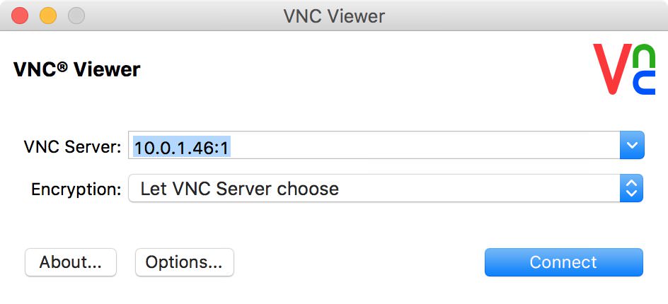
The VNC server is now running on display :1. Download the VNC Viewer client from realVNC for your Mac and open it up. Type in the IP of your Pi on the network and append the :1 screen, like this:
Type in the password for your Pi and you're set! You'll quickly notice it's not quite as snappy as if you were using your Pi with a physical display but it can get the job done.
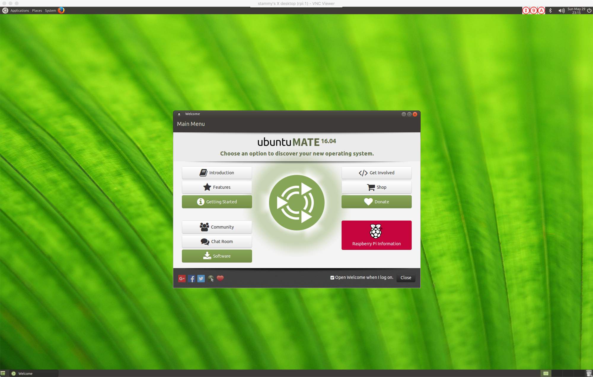
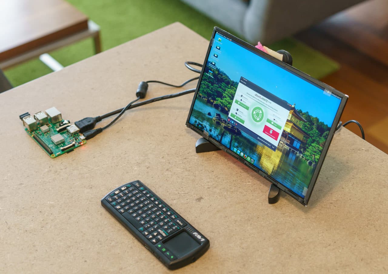
Ubuntu MATE 16.04 running on a Raspberry Pi 3 over VNC
Now you can fully control your Pi without the need for a hardware display. You will need to manually start the VNC server on the Pi whenever the Pi is rebooted. I'm usually logged in via SSH and rarely reboot so it's not a huge deal for me to run that line every now and then. But you can configure it to automatically run at boot.
But you might be thinking.. doesn't OS X have it's own screen sharing utility? Why do I need to install another app for this?
You're right! OS X is native VNC capable. To get this working we need to make the Pi discoverable via Bonjour and have it to broadcast it's new VNC support in a way that OS X can understand.
sudo apt-get install netatalk avahi-daemon
We're going to install netatalk4 which sets up the Apple Filing Protocol so we can also manipulate files on your Pi directly from the OS X Finder. If you're following this guide with Ubuntu MATE, you can leave off the avahi-daemon part as Ubuntu seems to come preinstalled with Avahi, the networking service discovery daemon.
At this point your Raspberry Pi should be visible and accessible on the local network with your Mac! However, to be able to see the screen sharing capability advertised here you'll need to modify a file:
sudo nano /etc/avahi/services/rfb.service
Paste this configuration below and save. We're telling the avahi daemon about RFB (remote framebuffer.. VNC basically) and what port it works on.
<?xml version="1.0" standalone='no'?>
<!DOCTYPE service-group SYSTEM "avahi-service.dtd">
<service-group>
  <name replace-wildcards="yes">%h</name>
  <service>
    <type>_rfb._tcp</type>
    <port>5901</port>
  </service>
</service-group>
And then restart the daemon:
sudo /etc/init.d/avahi-daemon restart
You should now be see a new Share Screen... button. Click on that, type in your Pi password and you can now easily VNC into your Pi natively.
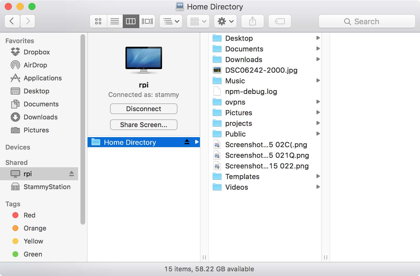
Raspberry Pi visible in the OS X Finder
This approach uses netatalk/AFP for sharing your Pi on the network so it will only work for Macs. If you'd like to share files for Windows machines, you'd want to setup Samba sharing. Also, AFP is technically deprecated, so a future-proof solution would be to setup SMB2... but I've always had a heck of a time getting it to work flawlessly and AFP works great for now.
Taking a look around
Let's build something
Turning it into a NAS
Now that you have your Pi and its files completely accessible via the OS X Finder, wouldn't it be neat to add more storage to your Pi, share that volume and backup to it? While I personally don't use my Pi for this — I setup a larger Synology 4-disk NAS system for my terabytes of photos — it can be done with a Raspberry Pi. Just don't expect it to be fast.
There are many small and energy efficient storage options from USB sticks to external laptop and desktop hard drives and SSDs. Keep in mind that the Raspberry Pi 3 only has USB 2.0 so you won't get the entire speed benefit of an SSD. And for the smaller drives that don't require their own power source, you will still actually want to plug it into a powered USB hub before plugging into the Pi to make sure you don't cause stability problems by stealing too much juice from the Pi itself.
The Raspberry Pi ended up getting so popular that Western Digital actually created a more efficient drive just for the Pi. Called the WD PiDrive it's a 314GB hard drive (314GB as in π, get it?) with a native 7mm USB connection. Unfortunately, it's pricey for how many gigabytes you get.
As you might expect with a real NAS, you can connect the Raspberry Pi to a UPS battery backup: either a real desktop-class UPS or a tiny add-on board like this or this that sits on top of the Pi and has a cell-phone battery with enough battery to let your Pi run for a few hours and safely shut down.
If you don't need the data portion of a real UPS system (being able to tell your Pi it's now running on battery and should shut off soon), you can just get a good USB battery pack that you always keep plugged in. Make sure you get a reputable one with the appropriate circuitry to support pass-through charging or build your own with this PowerBoost circuit and a 3.7V LiPo battery.
You can also setup your Pi to be a Time Machine backup destination on the network and you can even install CrashPlan to have all your Pi's files backed up to the cloud as well. But be warned it won't be particularly fast.
Mounting and sharing a USB drive
Regardless of what drive you get, you'll want to mount it and have netatalk share it so your Mac can access it. While Ubuntu MATE has some automounting stuff, I prefer to disable it and proceed the old-fashioned way. On Ubuntu MATE (not via SSH, you technically can with gsettings but it didn't work for me), type dconf-editor in the terminal to open the GUI dconf editor. Browse to org.gnome.desktop.media-handling in the left pane and uncheck automount and automount-open. Reboot.
-
Prepare your USB device by formatting it to ExFAT if it's not already. If you're not using Ubuntu MATE on your Pi, you will want to install this package to add support for ExFAT mounting:
sudo apt-get install exfat-fuse -
Plug in your USB device and type in
sudo blkid:stammy@rpi:~$ sudo blkid [sudo] password for stammy: /dev/mmcblk0: PTUUID="580a66ff" PTTYPE="dos" /dev/mmcblk0p1: SEC_TYPE="msdos" LABEL="PI_BOOT" UUID="4442-965D" TYPE="vfat" PARTUUID="580a66ff-01" /dev/mmcblk0p2: LABEL="PI_ROOT" UUID="e440adac-fcf9-4b68-9f94-6bfd030f60b3" TYPE="ext4" PARTUUID="580a66ff-02" /dev/sda1: UUID="9C33-6BBD" TYPE="exfat" -
We're looking for the UUID of the USB device so we can mount the drive based on it's unique id instead of it's location, so it will always mount flawlessly. In this case my drive is the last line with type
exfat, since it is a large 128GB SDXC card that I plugged in (not the micro-SD card but a USB card reader and SD card just to test this out). You can verify that this is the correct line item by ejecting and running thesudo blkidcommand again to see that the line vanishes. -
Create a new directory where we will mount the drive and then have your user account own it. If you are using the default pi username it will just be the following:
sudo mkdir /usb-drive sudo chown -R pi:pi /usb-drive -
Now for the real work, we need to add a line to our file systems table file. It is very important that this is typed correctly with the correct UUID and filesystem type for your drive. If this is incorrect your Raspberry Pi will get stuck at boot and you won't even be able to SSH in, you'll have to enter emergency mode to fix the file.
sudo vim /etc/fstab
-
Now add this line to the bottom of your fstab file, making sure to replace XXXX-XXXX with the UUID from the blkid command earlier and using the correct file system type (vfat, exfat, etc):
UUID=XXXX-XXXX /usb-drive exfat auto,nofail,uid=1000,gid=100,umask=0002,rw 0 0 -
Now we'll add this new drive as an item for netatalk to share. You'll need to edit this file:
sudo vim /etc/netatalk/AppleVolumes.default
-
Scroll to the very bottom and add this line representing the new persistent mount point for your USB storage device:
/usb-drive "USB Drive" -
Reboot. Your drive should now be shared and accessible on the network!

Benchmarking, overclocking and cooling
While I won't dwell on this too much, it's possible to overclock your Raspberry Pi to achieve higher CPU and RAM speeds. Why would you want to overclock your Pi? You might want to squeeze some extra performance from a CPU-limited process like video transcoding or the like. Or you might just want to see if you can overclock it for fun.
There's a simple Pi benchmark script that includes overclocking documentation so you can run before and after your overclock to measure benefits. There are also quite a few guides on the topic if you're really curious: Raspberry Pi 3 Overclocking and Pi 3 Overclocking, Stability Testing & Cooling. However, do not attempt overclocking without adding additional cooling to the Raspberry Pi CPU and RAM.
Heatsinks
Actually, even if you don't overclock your Pi but you put it through its paces or place it in a closed case you will still benefit from adding some heatsinks to your Pi. They're not absolutely required, but I sleep better at night knowing my Pi is nice and cool. Also, I used to overclock and watercool all my computers over a decade ago so I can't help but enhance my Pi's cooling situation.
While you could go a bit extreme with a massive heatsink and fan, peltier setup or even a custom watercooling contraption, it's all bound to be overkill unless you are doing some crazy hardware voltage modifications to your Pi. I'm assuming that's not you and just a simple heatsink will do.
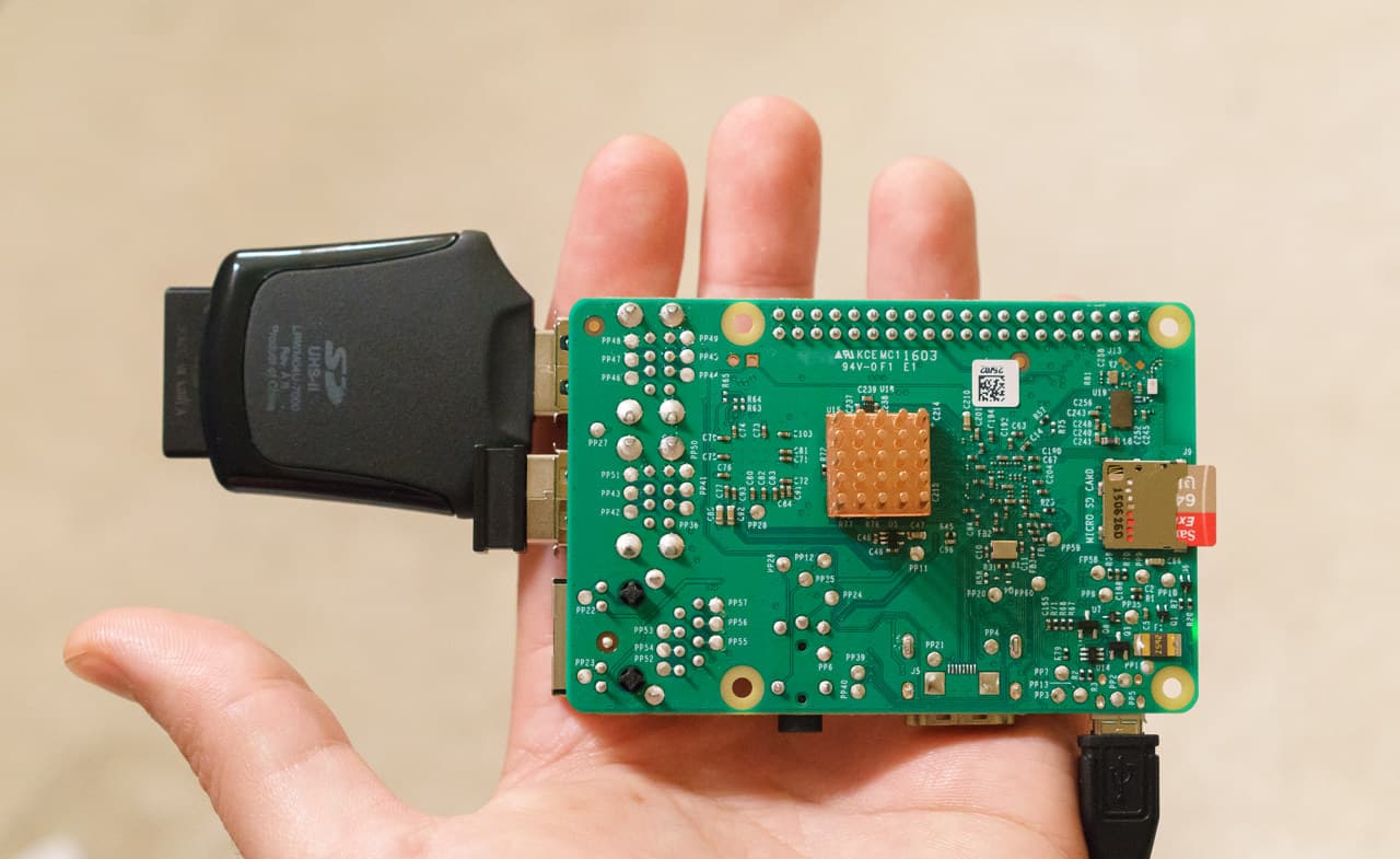
There are 2 main chips to consider for cooling: The primary SoC that's on the top of the board and the RAM chip underneath the board. There is also a smaller chip that gets a bit warm near the USB ports and that's the USB and Ethernet controller. I did a bit of research and eventually ended up getting some high-quality (albeit pricey) copper RAM heatsinks and MOSFET heatsinks from ENZOTECH. The RAM heatsinks fit well over the SoC and the RAM, but you can also do the same by just placing 4 of the tiny MOSFET heatsinks on each chip.
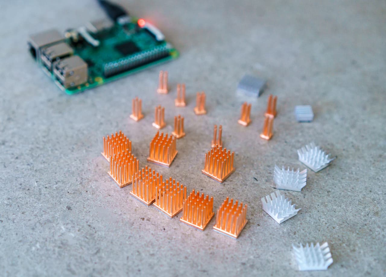
Unfortunately, they are a bit tall so having this on the underside of your Pi can limit your case mounting options. I also got a set of low profile aluminum heatsinks that would work as well.
With my Pi now heatsink'd up I can let it handle just about any task and not worry about it overheating. You can also get a 5V fan to blow over the heatsinks and use a script to only spin it up when it gets hot.
Working with the I/O pins
Pi electronics 101
Time for the fun part — tinkering with some electronics and the Pi's General Purpose I/O (GPIO) pins!
The Pi 3 — and Pi Zero, just without the connector pins — has 40 pins, but 26 of them are GPIO pins accessible to program. The other pins are ground (8), 5V (2), 3.3V (2) and reserved EEPROM pins (2).
There's a lot you can do with these pins. You can program any GPIO pin on or off (high or low) which provides 3.3V at a max current of around 50mA5. You can also have your program accept input on these pins, such as when connecting a sensor, switch or other device.
However, 50mA off a 3.3V pin is really not a lot to power anything. If you need a bit more juice, there's the two 5V pins which come straight from the same power source powering the Pi, minus however much current the Pi consumes. So with a 2.5A power supply, subtract about 1A for general Pi use with some small devices plugged in and you can probably consume a max of 1.5A off those pins.
Instead, the GPIO pin output should just be used as a signal to switch something on but not power it. If you're going to need to power anything more than an LED, you're going to want to use an external power source and something like a transistor, FET or relay. There are tons of electronics and Raspberry Pi guides that cover all of this in detail, but now that you have a primer let's build something simple!
Parts
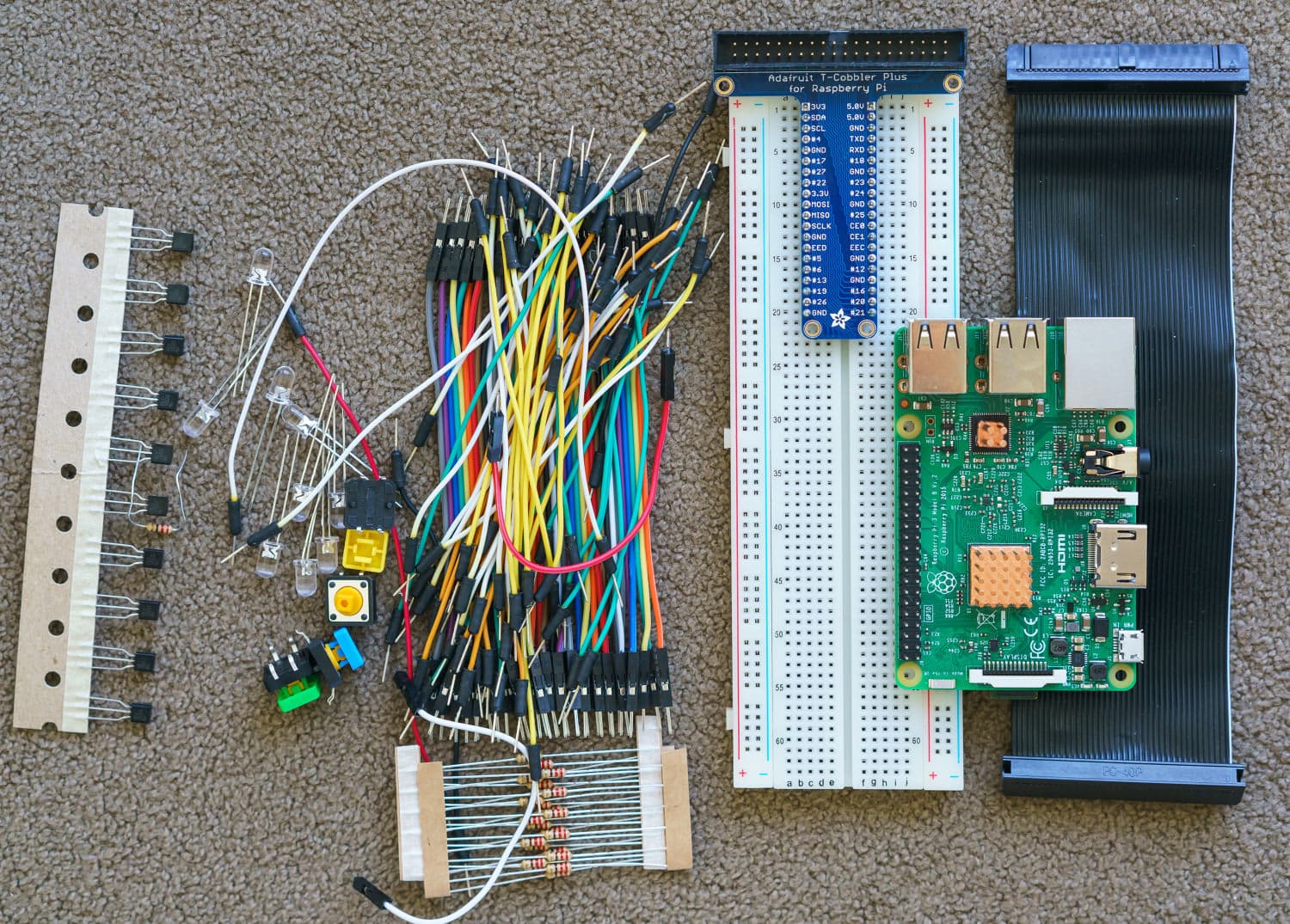
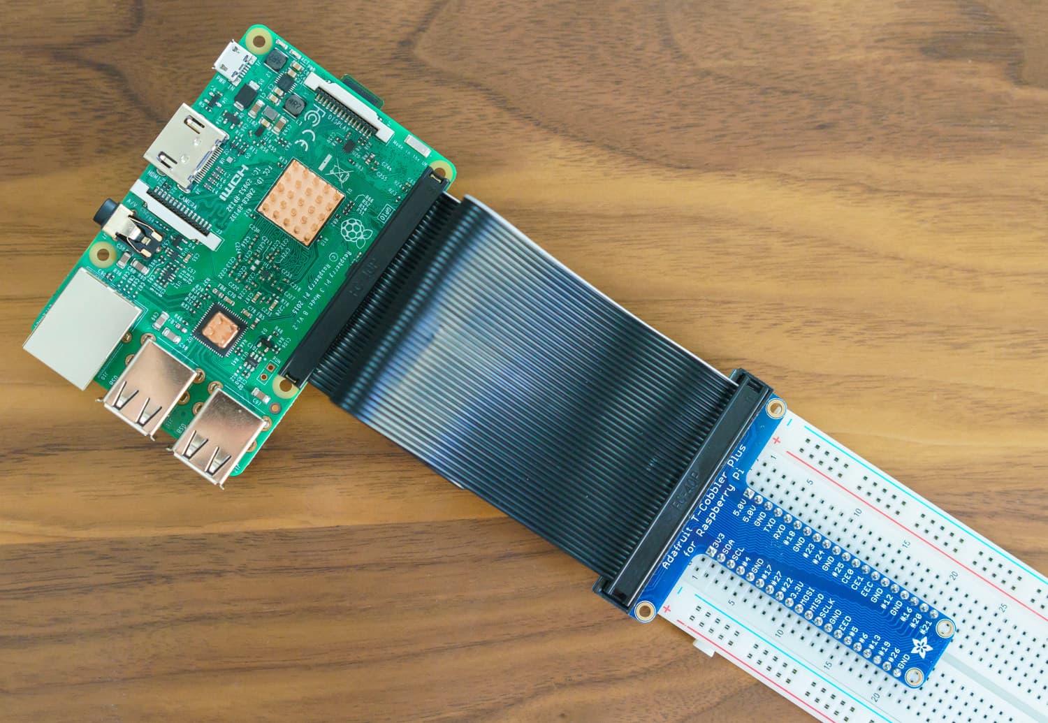
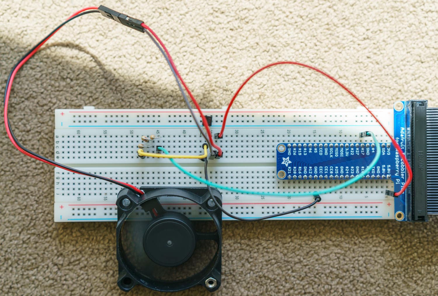
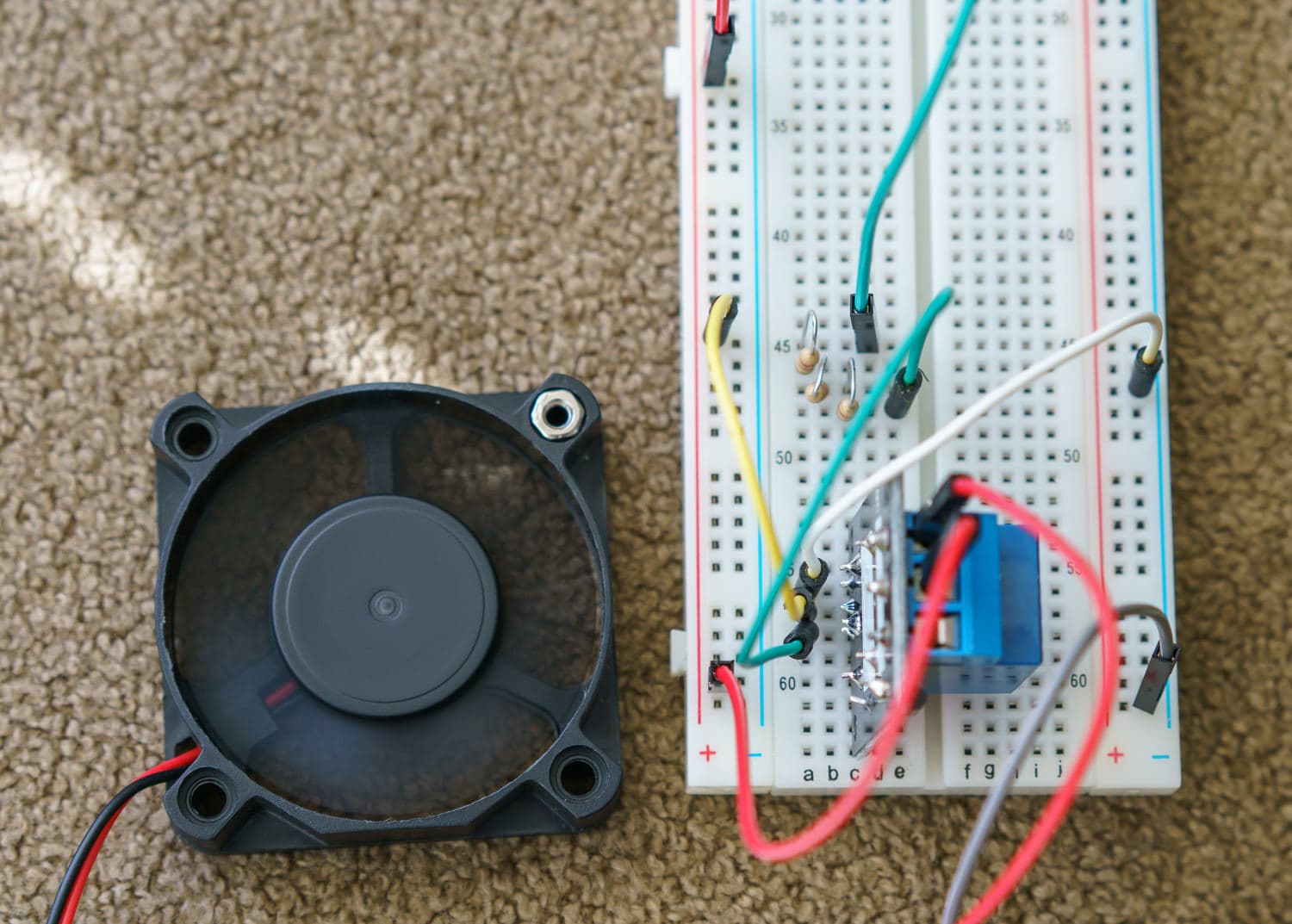
To make things easier for tinkering I purchased a breadboard so I could prototype little circuits without soldering. I also purchased a T-Cobbler that directly connects the Raspberry Pi pins to the breadboard. And of course various LEDs, wires, transistors, resistors and buttons to play with.

Setup & powering an LED
First, attach the T-Cobbler board to the breadboard and then to the Pi with the ribbon cable. Make sure the ribbon cable's white wire connects to the corner side of the Pi. Aside from making it easy to physically connect things with the breadboard, the T-Cobbler board also provides you with the GPIO pin labels.
It's important to note how the breadboard works so you don't short anything out by accident. On the breadboard, the outer rails (marked by blue and red lines) run the length of the board. These are the power rails where you can connect GND to the - blue line with a jumper cable and 5V to the + red line (or even an external power source instead of from the Pi) and be able to access those lines throughout the length of the board.
The lines between those outer rails — the terminal strips — run perpendicular. So if you want to plug into GPIO pin #17 for example, you would put a jumper cable anywhere to the left of that pin, but not the blue or red outer rails. You can read more about breadboards in this article.
Now let's just try to power an LED. Nothing special for now, we'll just connect the LED to the 5V source that comes directly from the power adapter connected to the Pi.
But first we should be cautious about how much voltage and current we supply to the LED; we don't want to burn it out. In my case I got a 25mA 3.4V UV purple LED. I used this LED resistor calculator to find out exactly what I needed. It said 68Ω, but I could only find a larger 220Ω resistor at the time. No biggie, it just won't be as bright.
Resistors don't have polarity so it doesn't matter which way they are used. LEDs do however. There's the cathode (-) that is easy to identify as it's the shorter wire from the LED and there is a flat side of the LED identifying the cathode. The longer wire coming from the LED is the anode (+). This can be done various ways with the breadboard, but I started by placing a jumper from GND to the blue power rail and then plugging the LED into the power rail, making sure that the short end of the LED (cathode) stayed on the negative blue rail. Then I connected the resistor from the 5V terminal strip on the breadboard that comes from the Pi to the positive red power rail. Now our LED will light up!
Control the LED
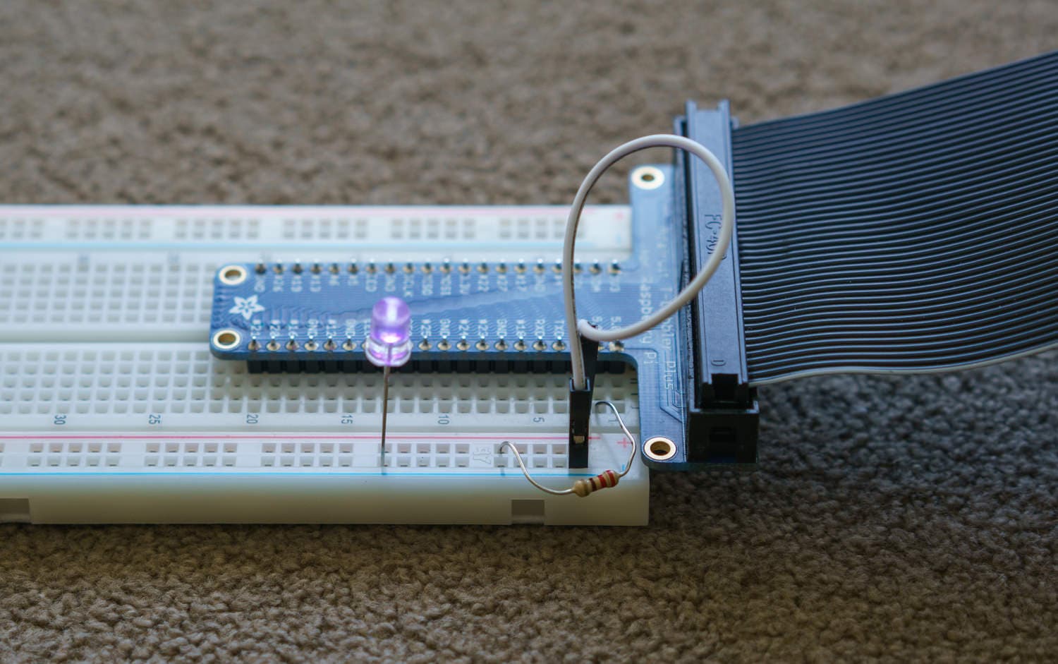
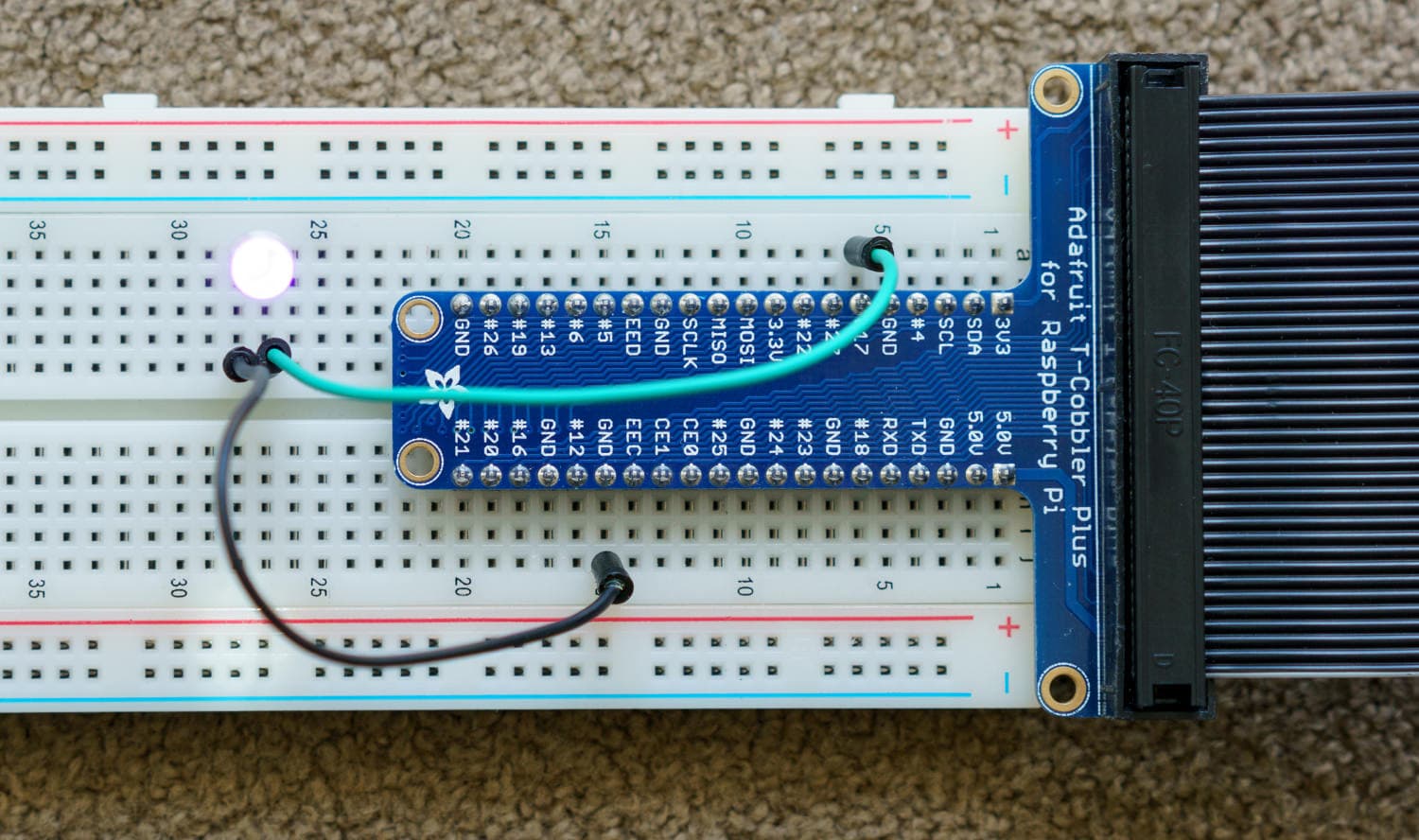
Okay now that we've got the basics out of the way, let's actually control the LED instead of having it on continuously. To do this we need to power it from a GPIO pin instead of the 5V line. Since the GPIO pin is 3.3V and our LED has about the same forward voltage, we can ditch the resistor now. As a word of caution, we can get away with powering the LED from the GPIO pin since it won't draw much current. Don't try to power anything other than an LED off a GPIO pin or it might damage your Pi.
This time we just need to connect the LED anode (the long wire) to GPIO pin 17 and the cathode to GND. You can see how I used jumpers to get this done in the photo below. As for why I used GPIO pin 17: no reason, you can pick any GPIO pin and program it below.
Then we SSH into our Pi — or directly on it if you've got a display hooked up or are using VNC — and open up the python interpreter so we can use the python GPIO library. First we need import that library. It should be included in your OS automatically if you're using Ubuntu MATE or Raspbian Jessie.
stammy@rpi:~$ python
Python 2.7.11+ (default, Apr 17 2016, 14:00:29)
[GCC 5.3.1 20160413] on linux2
Type "help", "copyright", "credits" or "license" for more information.
>>> import RPi.GPIO as GPIO
>>> GPIO.setmode(GPIO.BCM)
>>> GPIO.setup(17, GPIO.OUT)
>>> GPIO.output(17, True)
>>> GPIO.output(17, False)
Then we need to set the pin mode. This determines what we mean when we provide a GPIO pin number: either by the physical pin position (GPIO.BOARD), or by the Broadcom pin number (GPIO.BCM). The latter is listed on the T-Cobbler for us so I provided the GPIO.BCM mode. Then we setup() each GPIO pin to be used and tell the Pi if it will be used for input or output (GPIO.IN or GPIO.OUT). We'll go with output since we just want to power the LED instead of listen for an input signal.
And now we can finally we can turn the LED on and off with these commands: GPIO.output(17, True) and GPIO.output(17, False). Go ahead and try it a few times! and think about how we're talking to a tiny computer over a network and having it control our electronics for us. Pretty neat. Despite everything being an app or connected device these days it's still fun to be able to control something simple like this.
This python GPIO library provides the essential foundation for interfacing with the i/o pins on your Pi. There is also a popular C library called WiringPi and one called gpiozero, which provides higher-level functionality for quickly setting up common output and input components like LEDs, buttons, sensors and more. Definitely worth checking out for more advanced items.
And while I just wanted to show the basics using the GPIO library in the python interpreter, you can of course write them as a .python file and run it as you please. There's a whole lot more you can do when actually writing your python programs.
Using a transistor
Remember how I mentioned that we don't really want to drive more than a simple LED directly off the GPIO pins? Since the GPIO pins can't provide much voltage or current6 you should find other means to trigger and power your connected components.
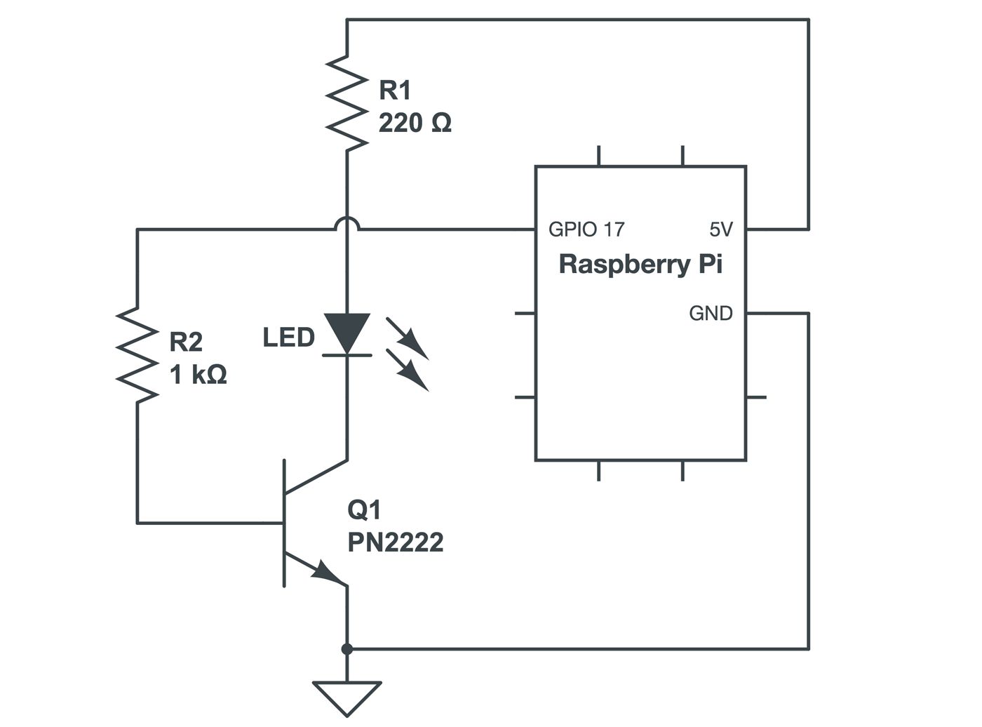
One way to control your components is with a transistor. I'm using a basic BJT (bipolar junction transistor) NPN (negative-positive-negative) transistor, the PN2222. It can handle up to a peak of 40 Volts(!) at 1A, more than enough to drive something like a small motor, various lights, and so on. They only need a tiny amount of current to flip on, thus saving your GPIO pins from doing the heavy lifting.
Typically you should also use a resistor between the transistor and the GPIO pin to reduce the current it draws. There is a bit more to it — like how the amount of current applied to the base can vary the collector current as the transistor acts as a simple amplifier, up to a "saturation" point — but that's best left for some extra reading if you're curious.
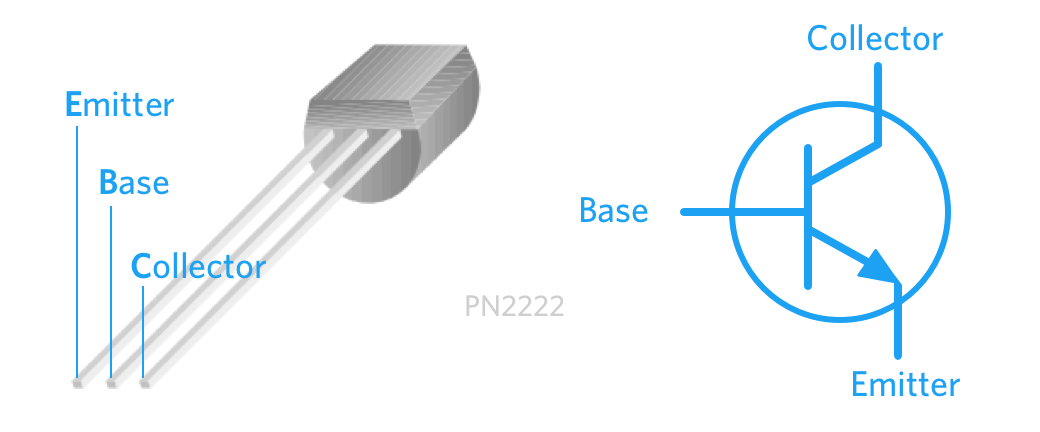
Okay so we have 3 pins on our transistor: emitter, base, collector (EBC). It's important to note the exact pin layout as it varies by transistor. If you're looking at the flat side of the PN2222 NPN transistor, we have EBC from left to right. The middle base pin is what actually causes the transistor to trigger, making the normally open emitter and collector closed. This is the opposite behavior from a PNP transistor, with some extra nuances.
While this circuit works for this very simple use, technically you would want to add a pull-down resistor from the base to ground to get it to switch off faster and for other reasons.
We want to connect the base pin to our GPIO pin 17 along with a resistor. I wanted to use larger resistor but only had my same 220Ω resistors, so I put a few in series. This introduces enough resistance to lower the current used by the transistor on the GPIO pin but have enough juice to saturate the transistor into a fully on state.
Current flows from the collector to the emitter, so I connected a jumper cable from GND to the emitter and then placed the LED7 between the Pi's 5V pin and the collector. Then connect the LED anode to the 5V line and the cathode (the flat side of the LED) to the transistor's collector with that same 220Ω resistor in between.
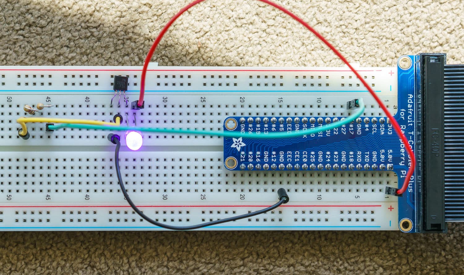
I forgot to add a resistor from in front of the LED, so it was powered by 5V directly here. No issues but you don't want to be running it like this for more than a bit.
Now you can run the same GPIO.output() commands from earlier to switch the LED on and off, via the NPN transistor! This is a safer way to control small devices off your GPIO pins.
But what should you do if you need something even heavier duty for controlling a larger motor, high-wattage LED or anything demanding more than an amp of continuous current? You can use a beefier transistor like a heavy duty BJT, darlington or a MOSFET8. There are various differences between them that I'm not experienced enough to comment on. But I do know the about the next option: relays!
Use a relay
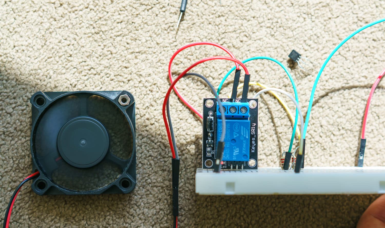
Lets get a relay working for our last experiment. There are several kinds from electromechanical to solid state and more, but the concept is the same: it will close or open any circuit you connect it to when triggered. The difference between our earlier BJT NPN transistor is that it's only on or off (no amplification characteristics) and the circuit you switch on is entirely separate to the switching logic (at least with electromechanical relays) so most relays can support much larger voltages while not interacting with your low voltage circuit. Okay I'm rambling a bit but basically this is what you want if you want to run an even larger device, like a 120V lamp for example (assuming your relay is rated for that).
I ended up getting an electromechanical relay that was preassembled to just need a control signal to make it easy to get started — it wires up just like our previous transistor. It bakes in the necessary transistor and some safeguards like a flyback spike protection diode for the relay coil. Again, there's more to read about on the EE side here if you're interested.
What's next?
My intent with this section was to fall somewhere between informative overview and step-by-step. There's obviously a ton of detail I flew past and I only showed the most basic examples. But now you get to have fun trying out new circuits on your own! I love this stuff as you can probably tell.. I took a few EE classes in college long ago.
While we only touched on using a single GPIO pin as output, there's lots to learn about using them for input as well. Here's some more reading about Raspberry Pi GPIO electronics to keep you busy:
- Learn more about circuits at Khan Academy
- Connect a button and use it as an input
- Control a servo motor
- Hook up a motion sensor as an input and record a video when motion is detected.
- Use an iOS app and Pi server like Cayenne or MyPi to control your connected relays, sensors and other GPIO devices on your phone or the web. Or do it yourself with the self-hosted Pi GPIO web interface
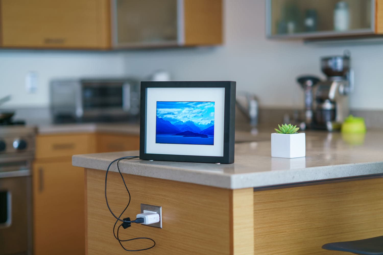
Building a digital photo frame
with a 10" 1920x1200 display
I wanted to do a real project with this Raspberry Pi. Something I would actually use around the house. I had narrowed it down to either a smart mirror or a digital photo frame.
While there is definitely a strong cool factor with smart mirrors, I soon realized just would not get real value out of it. There's not much information I care about enough to be on an ambient display that I can't interact with.
Weather, news headlines, email subject lines? The majority of those require me to pull out my phone to actually learn more. And I wouldn't put anything too personal on there that guests might see (like work emails). There might be something there in the future when it's easy to setup eye tracking and have the device detect when my eye is dwelling on and open a browser to learn more about that news headline, or read it out loud to me. But for now I already check my phone a million times per day and I already get my news read to me with the Amazon Echo every morning.
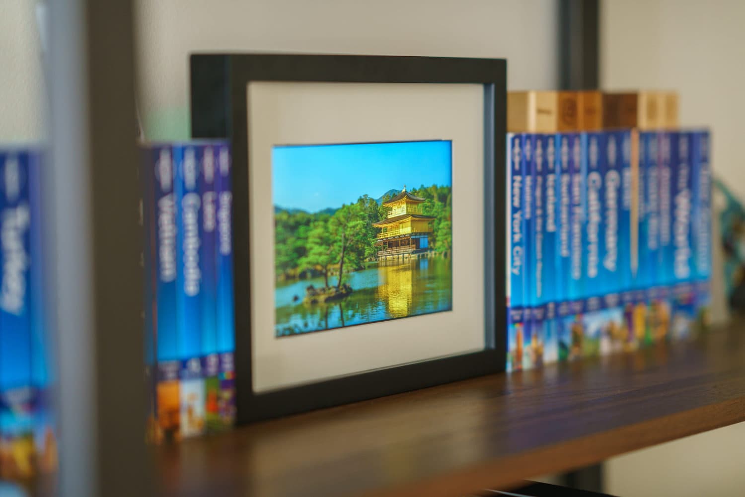
A digital photo frame on the other hand has an aesthetic value for me and given that I'm a photographer as well, it's right up my alley. It will fit in nicely with the other framed photos and travel books throughout my house.
We're going to need a display
Now the obvious question — where was I going to put this and what kind of display would I need? There's also the question of whether I wanted a touchscreen display. I decided to keep it simple, no touchscreen. Though I did initially think it would be neat to swipe between photos. Going with a regular display also makes mounting the display easier as I could put it behind glass.
As I began searching for displays I quickly realized that it was hard to find a high-resolution display. The majority seemed to be somewhere between 800x480 (like the official Raspberry Pi 7-inch touchscreen display) and 1280x800. I even found some folks using iPad 2 displays (9.7-inch 1024x768). Not bad but not terribly appealing to me. A low resolution screen would not do my photos justice, especially as I have gotten used to seeing them on high PPI displays.
I also knew I would be mounting this in a frame and put it on my bookshelf. While disassembling a regular desktop computer monitor is a popular route, I wanted something smaller and didn't want anything that required a bulky 120V cable and adapter. I needed a display that could be powered via a USB cable and accept an HDMI input.
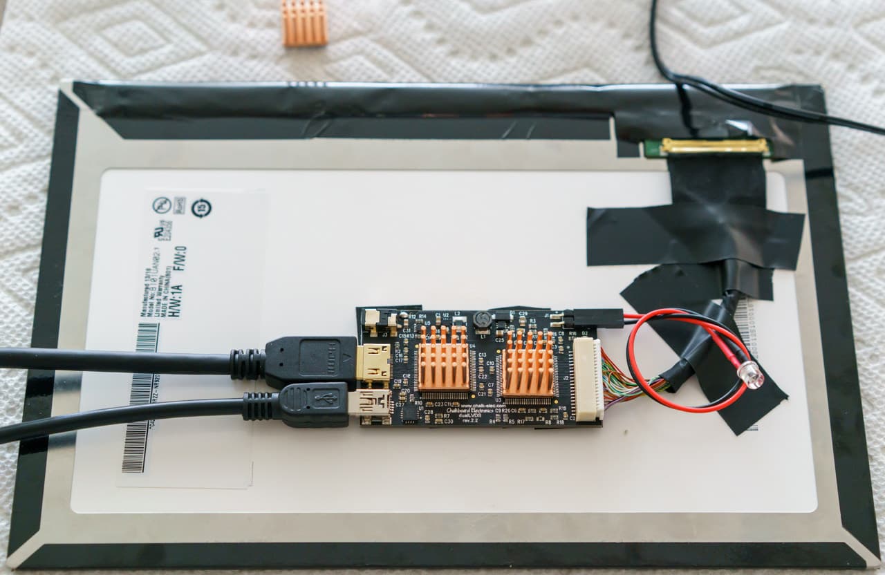
The maximum resolution the Pi can support is 1920x1200 so I wanted to get as close as possible in something around the 10" to 12" size. After lots of searching, I eventually stumbled across this 10-inch beauty from Chalk Elec. Yes, it's expensive at $140 USD for just the panel, but it was just what I was looking for. It's 1920x1200 and at 10 inches this makes it a ridiculous 226ppi panel. That's a tad better than the 218ppi 5K iMac.
I tested the display and everything was working great! I was just amazed at the resolution. It would have been overkill if I was going to use this for anything other than a photo frame. I would have had to use a lower resolution setting to make it comfortable to use for longer periods.
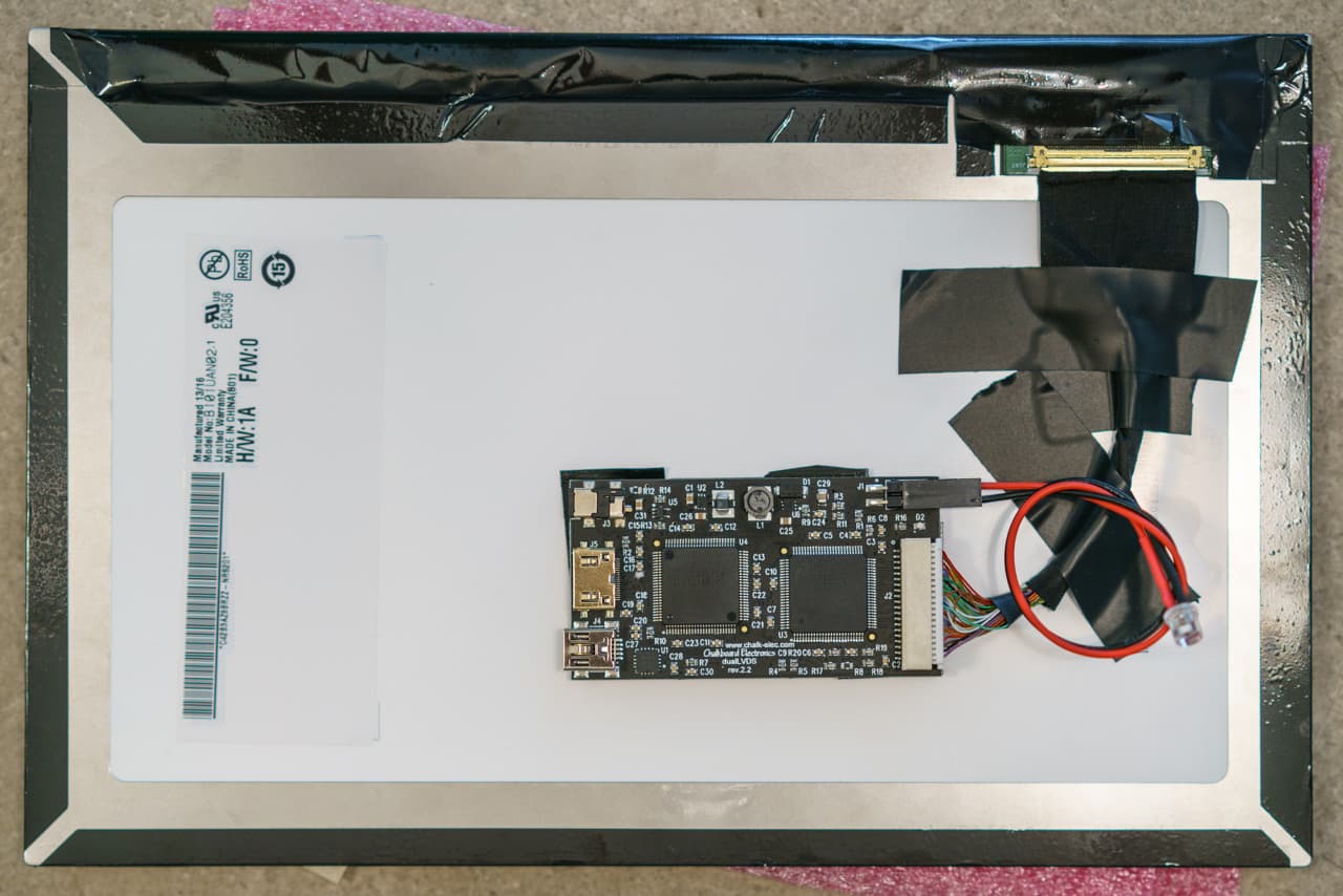
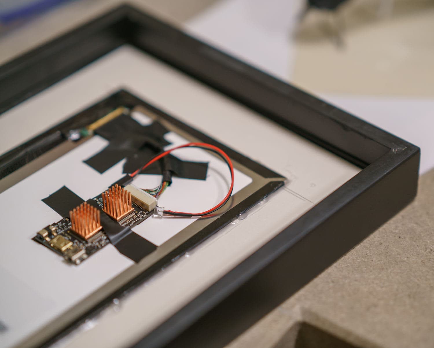
The display's controller board can accept power from either a dedicated wall adapter or from USB. I wanted to go with USB so I followed their instructions and soldered a jumper (0Ω resistor) where it says R12 to be able to accept USB power. And while I was tinkering with it I also decided to put heatsinks on the two LVDS chips as they got very hot when in use.
I was a bit nervous working with this board. The cable running to the display extremely short and delicate, whereas the huge HDMI cable is rather inflexible and heavy. I was quick to use some electrical tape to prevent the flat cable from getting plucked out and torn.
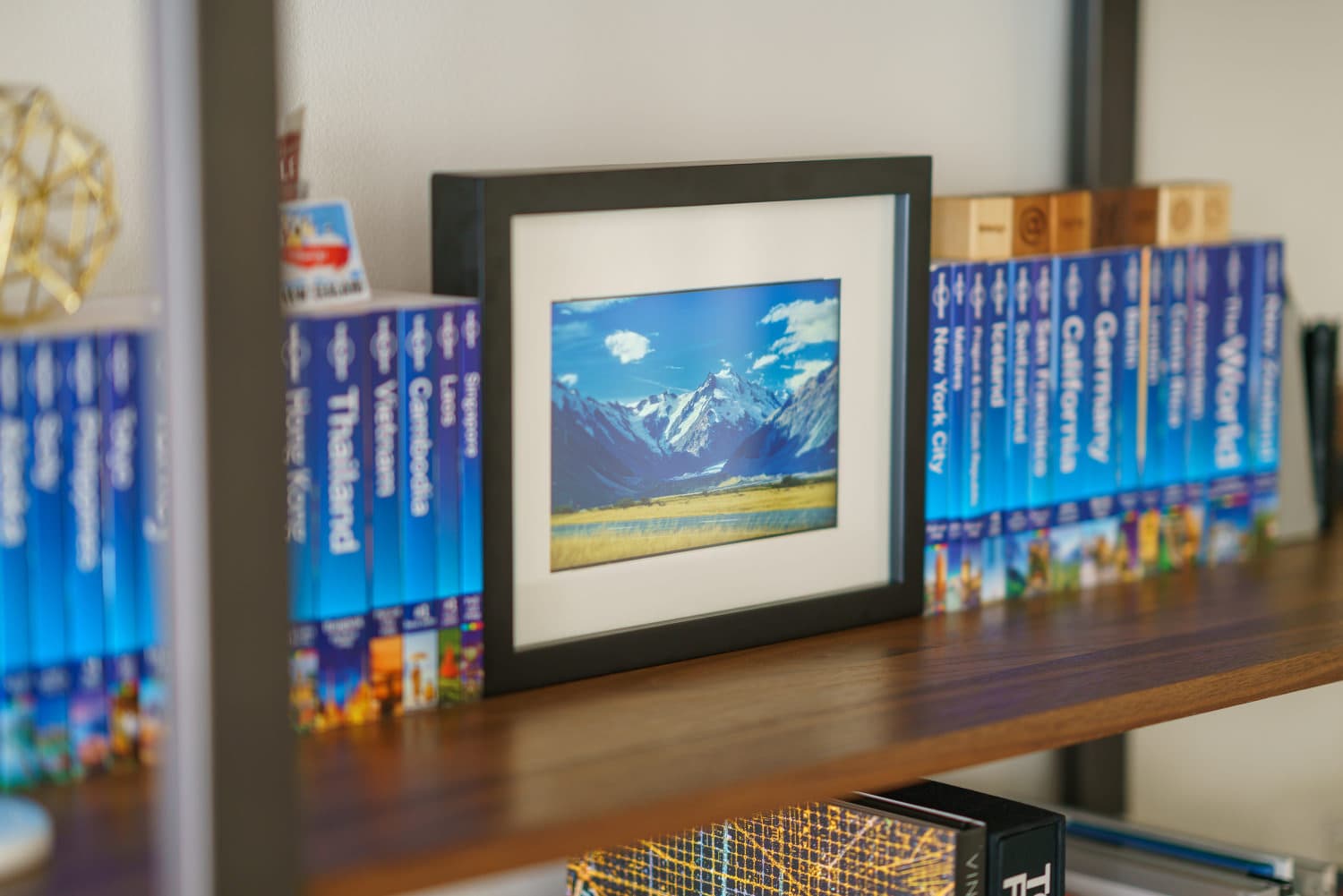
Mounting the display
Now that I had my functioning display, I needed to figure out how to mount it. I decided I wanted to go with a real photo frame with matting. I planned on putting it on my bookshelf. The original thought of hanging it on my wall was intriguing but hiding the cables would be tricky and I didn't feel like drilling into my wall and installing an up-to-code flush electrical outlet behind the mounting location.
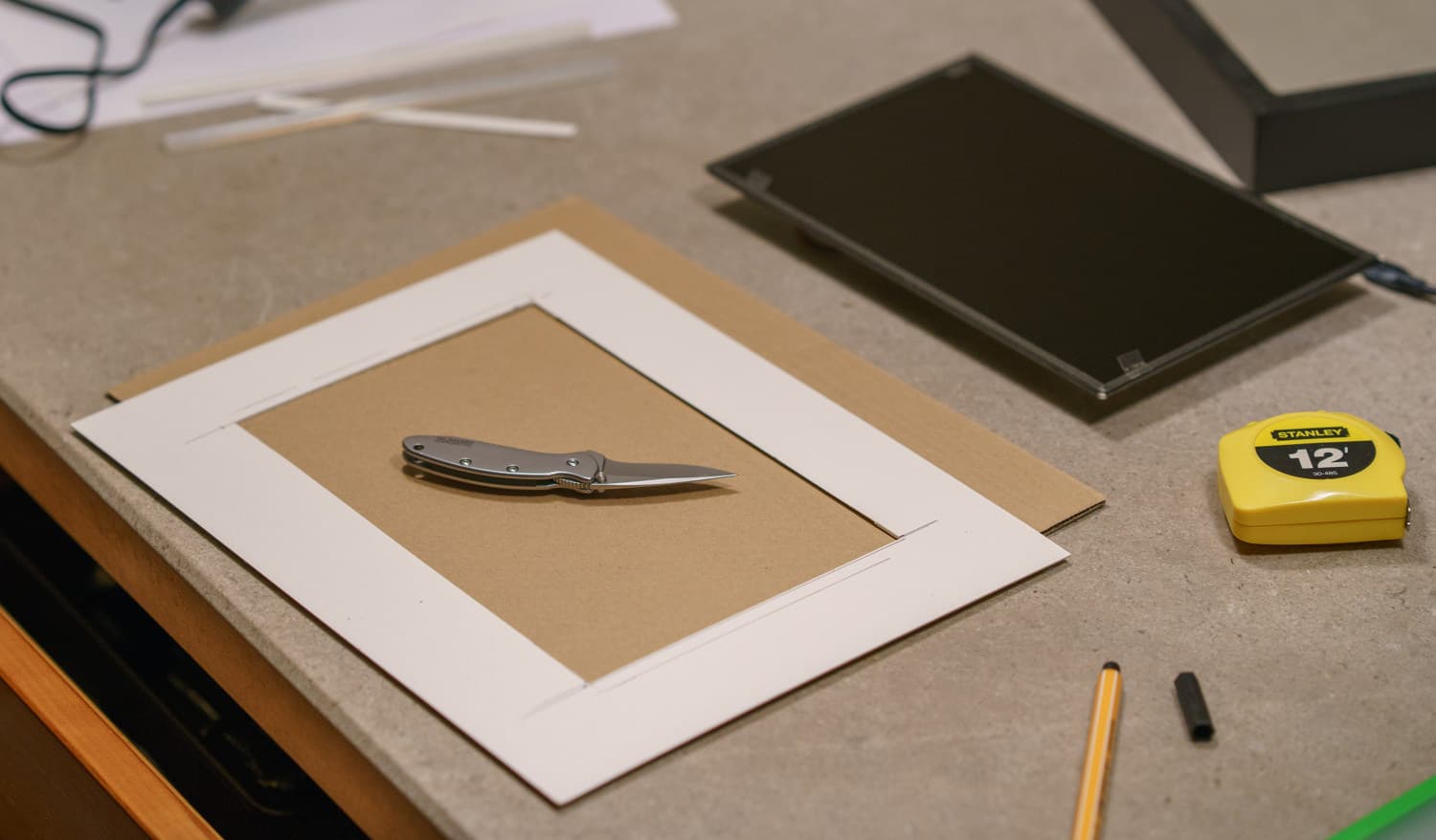
I went to a local frame store and picked up a 9" x 12" frame with matting. I carefully measured the viewport of the display and cut the sides of the matting to add room. This worked but the matting had a beveled cut so my cuts don't look natural . Eventually I will have the frame store custom cut the matting in the size I need, but this will do for now.
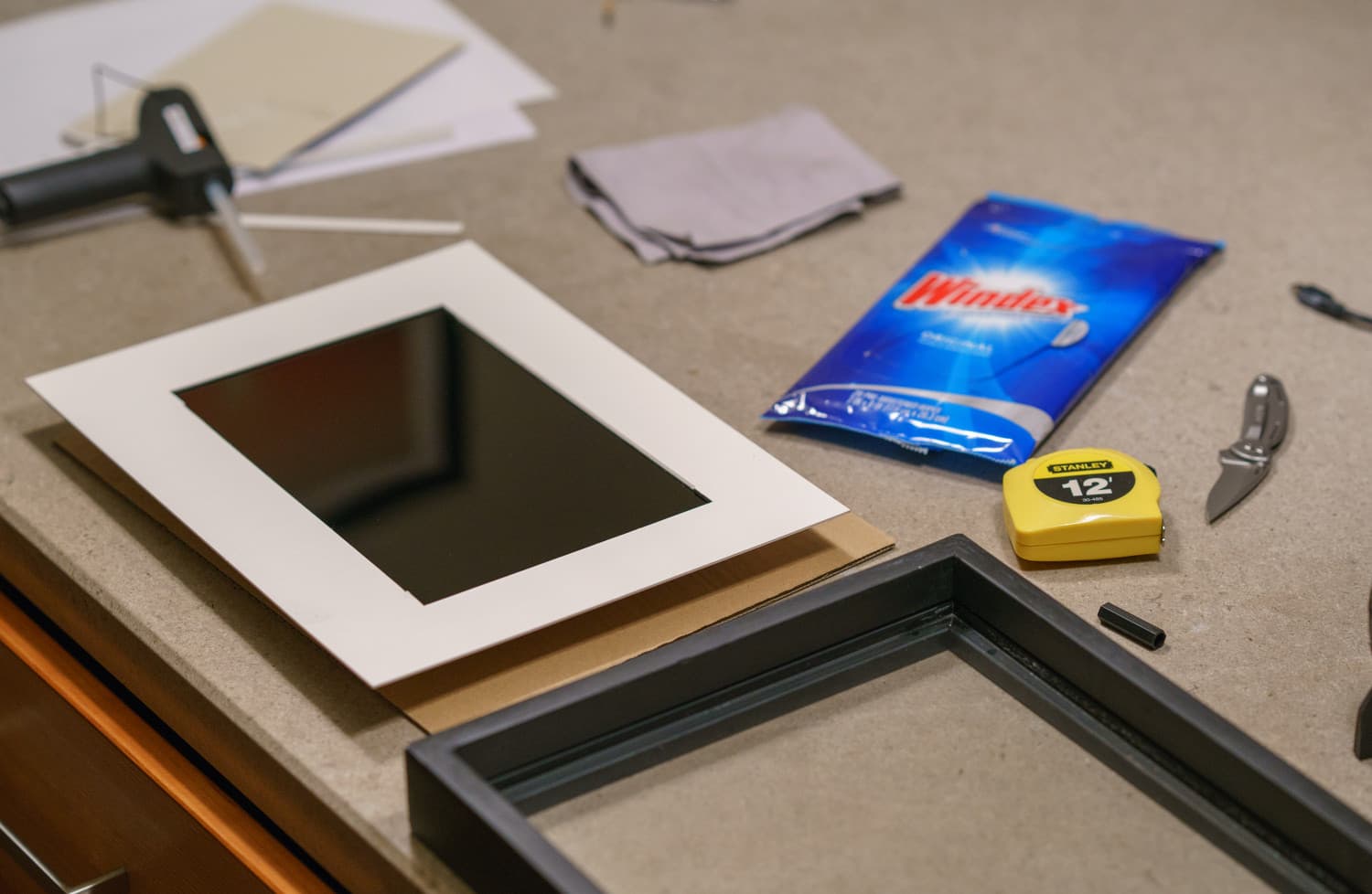
I then placed the display behind the matting. Fortunately, the bezel of the display came with a sticky foam so I just peeled that back and placed it on the matting. After the display was in place, I ran a thin line of hot glue around the sides.
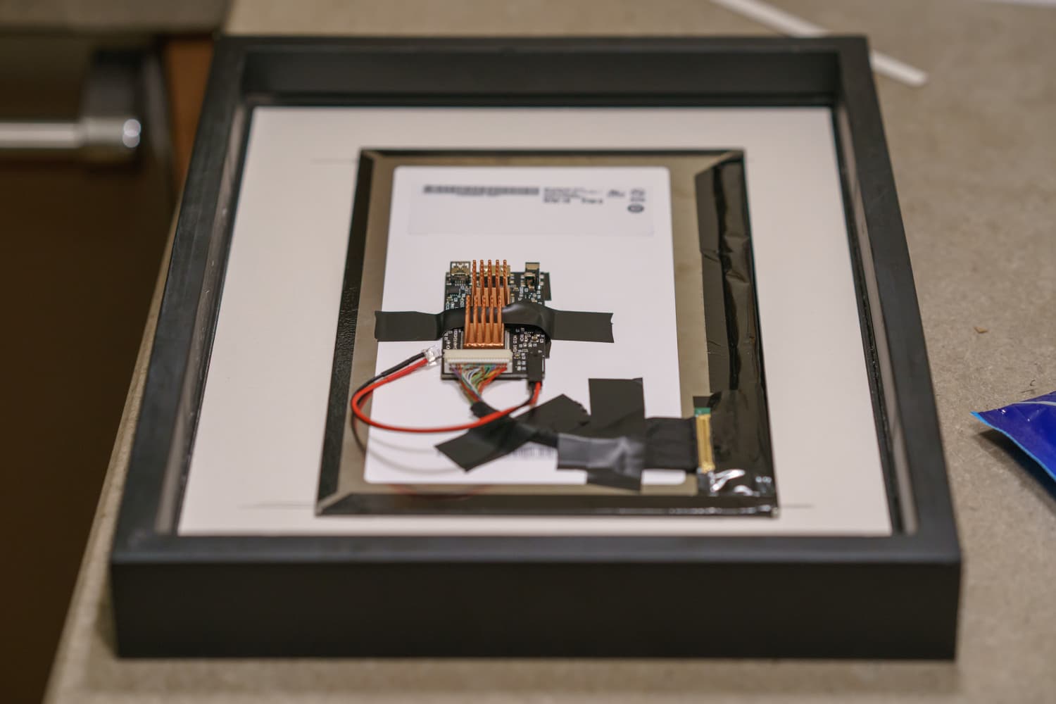
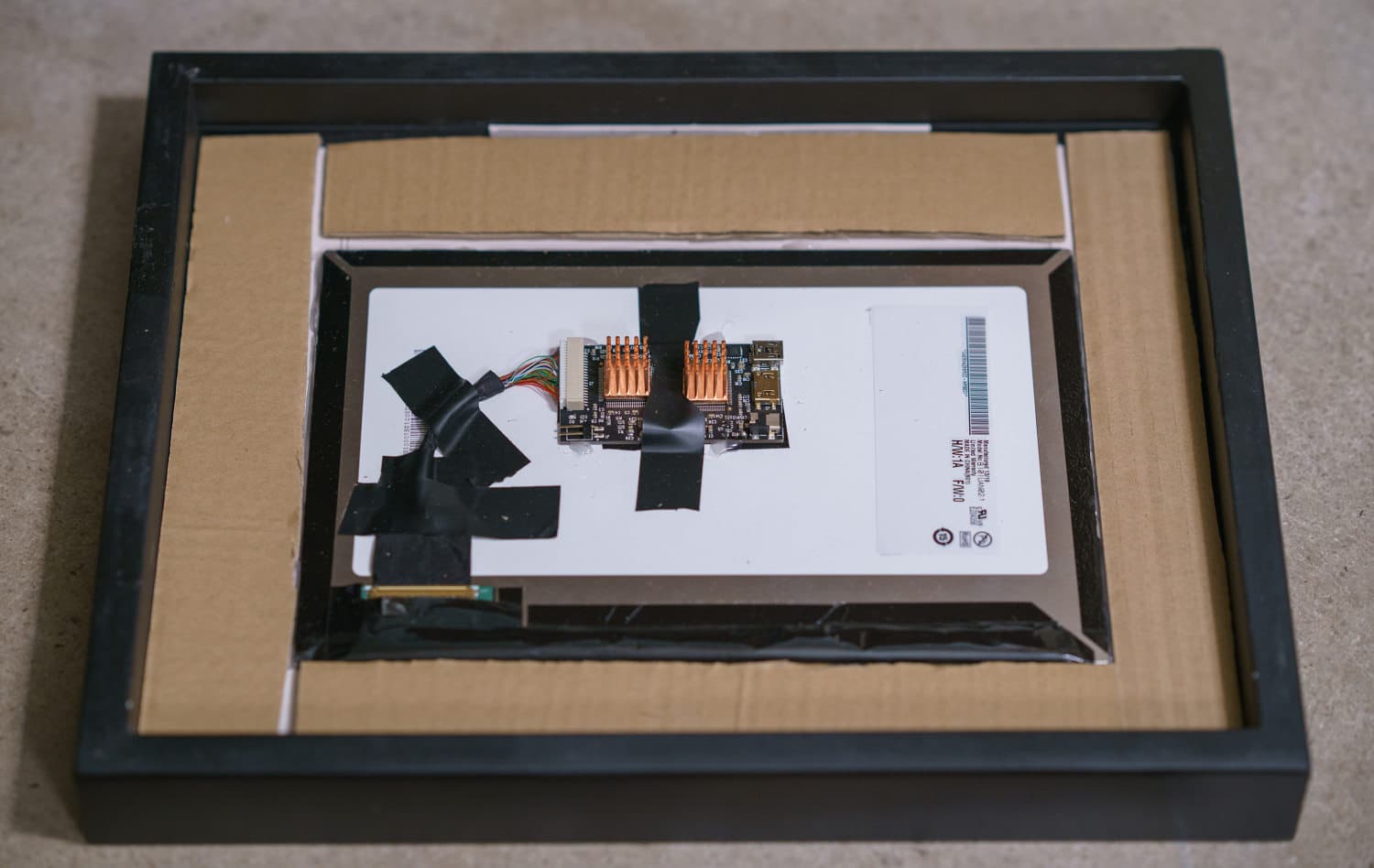
I cut peices of cardboard and put them alongside the display to reduce pressure on the display when I put the back of the frame on. I then cut a space for the cables and the controller board to peek through as well. I'm surprised how easily this part all came together. It actually looks pretty decent! Well, everything except for the hacky way I cut the frame backboard.. in hindsight I could have probably just cut a hole for the display's cable only instead of having it be against the display. I was just a bit concerned with moving that cable as it's pretty short and very fragile.
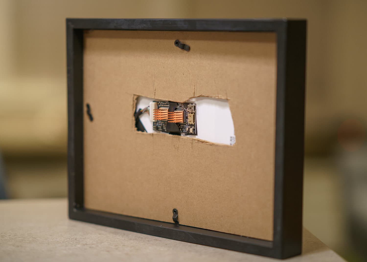
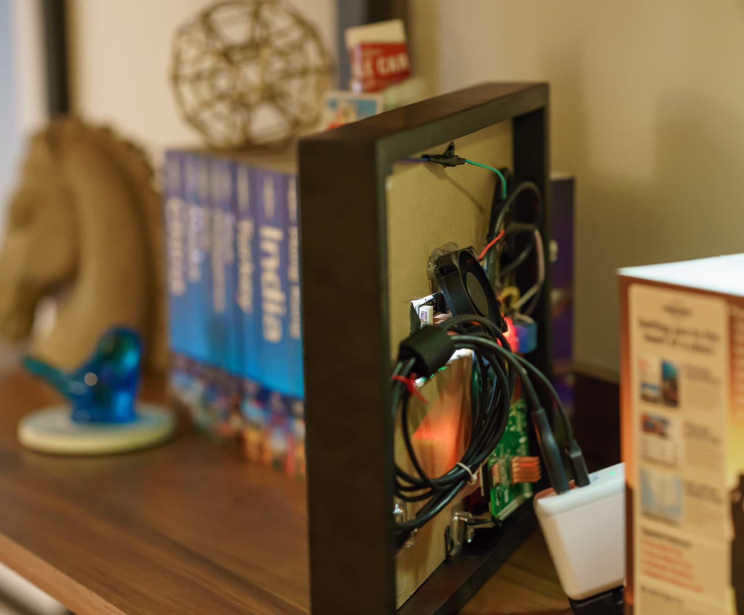
Mounting the Pi
With the back of the frame in place, I still had a bit of room to tuck the Pi away out of sight. The HDMI cable was pretty thick so that pretty much held the Pi in place on its own. I hot glued the cables in place to be safe. Then I added some small 3M plastic hooks to keep the Pi in place — one hooks into the Ethernet port and the other I attached with a small wire to the corner mounting hole.
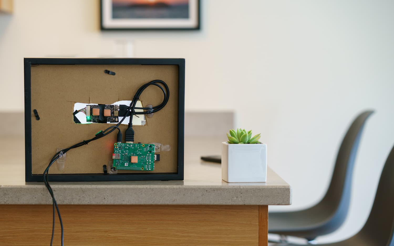
Now it was time to give it a test boot. I was powering the Pi and display off separate USB sources so that I had more than enough juice to spare for the Pi. Instead of having to find two USB power adapters, I opted for this great Anker dual USB adapter which provides 2.4 amps per USB port.
With the Pi Frame now up and running I had two challenges:
- Figure out how to display my photos in fullscreen
- Figure out how to turn the display and backlight off when needed.
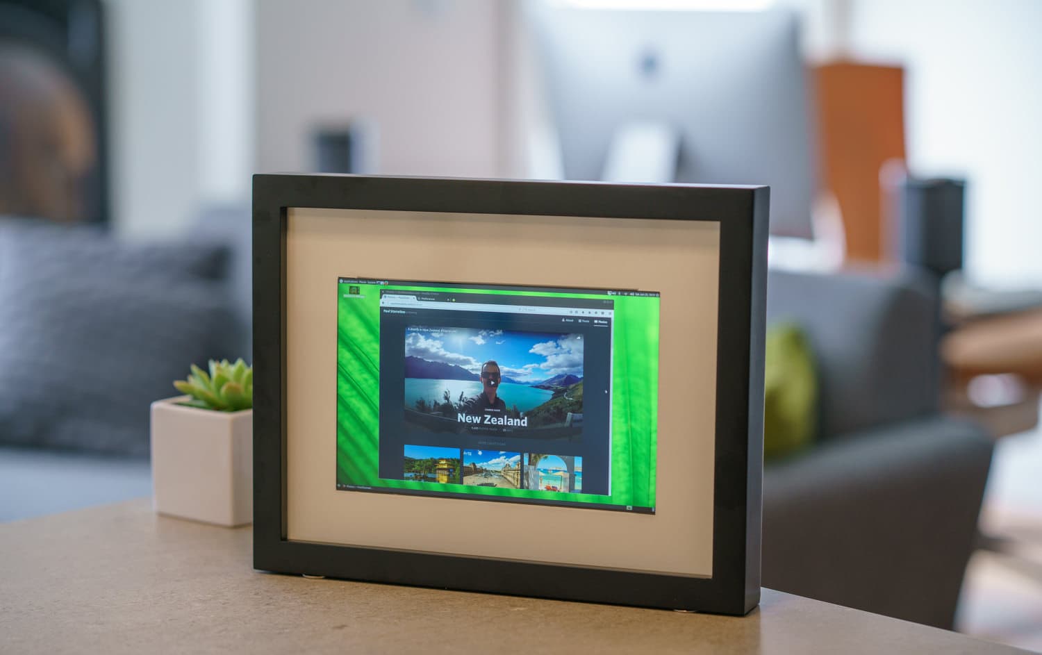
Displaying the photos
The traditional route for a digital photo frame is to have a synced photos folder with something like Dropbox or rsync and then use a fullscreen image viewer like feh or fbi. Both are rather no-frills setups.
I wanted to see if I could bypass the photo syncing portion of this and just use the Google Photos website. I've already professed my love for Google Photos so it would be great to use it here as well.
I would only need to have a browser that could display in fullscreen or kiosk mode. I decided to give Firefox a try, only because there is currently an issue with the latest Chromium crashing on Ubuntu MATE. There are also dedicated kiosk browsers like kweb and FullPageOS.
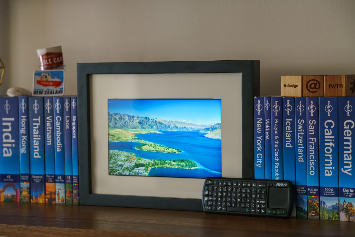
Fortunately, Firefox's native fullscreen mode did the trick. I just had to log into Google Photos, select an album and hide the mouse in the corner. To get photos to be the perfect aspect ratio to fill the 1920x1200 display and not have pillar or letterboxing, I created a new album and uploaded some of my travel photos cropped to a 16:10 aspect ratio. It worked perfectly!
I was able navigate between photos in the selected album using the left and right arrow keys. Google Photos also recently created a slideshow mode that I tested out. However, there were two issues with the slideshow mode to address. The first is that it puts a control box in the bottom left corner that does not hide. I ended up using the Stylish Firefox plugin to inject CSS to hide that box.
The other issue with slideshow mode is that it's a bit too fast for this use case. It seems to progress to the next photo every ~5 seconds. I'd much prefer something every few minutes or hours. I ended up not using slideshow mode. I can just hit the right arrow on the keyboard to get the next photo or video.
I decided to take a stab at automate this by writing and injecting some JavaScript into the page to change the photos for me every 10 minutes. I used the Firefox Greasemonkey add-on and wrote this script below. Unfortunately, when you get to the last photo in an album in Google Photos, the next arrow disappears and it does not loop you back to the beginning. So I had to have the script to detect when you got to the end and then go backwards until it hits the first photo and so on.
You can adjust the time by changing the 600000 number (10 minutes in milliseconds) on the last line.
// ==UserScript==
// @name        google photos slower slideshow
// @namespace   piframe
// @include     https://photos.google.com/album/*
// @version     1
// @grant       none
// ==/UserScript==

function next_or_prev() {
  window.direction = window.direction || 'forward';
  var next_el = document.getElementsByClassName("oJhm5 gMFQN")[0];
  var prev_el = document.getElementsByClassName("oJhm5 KUdGif")[0];

  if (direction == 'forward') {
    var css_display = window.getComputedStyle(next_el).getPropertyValue('display');
    if (css_display == 'block') {
      next_el.click();
    } else if (css_display == 'none') {
      window.direction = 'backward';
      next_or_prev();
    }
  } else if (direction == 'backward') {
    var css_display = window.getComputedStyle(prev_el).getPropertyValue('display');
    if (css_display == 'block') {
      prev_el.click();
    } else if (css_display == 'none') {
      window.direction = 'forward';
      next_or_prev();
    }
  }
}
window.setInterval(function(){next_or_prev()}, 600000);
Update: The issue with this approach is that it relies on the class names of the left and right arrows, which are bound to change with future Google Photos web deploys. I rewrote this script (below) to trigger a right arrow key event instead. It keeps trying to go to the next photo and if the URL doesn't change it figures it must be at the last photo so it goes to the first photo. This requires you to provide the URL of the first photo in the album you are using.
// ==UserScript==
// @name        google photos slower slideshow
// @namespace   piframe
// @include     https://photos.google.com/album/*
// @version     1
// @grant       none
// ==/UserScript==

// CHANGE first_photo TO USE THE URL OF THE FIRST PHOTO IN YOUR ALBUM
var first_photo = 'https://photos.google.com/album/XXXX/photo/XXXX';
function pressKey() {
  var key = 39; // right arrow keycode
  var body = document.getElementsByTagName('body')[0];
  if(document.createEventObject) {
    var eventObj = document.createEventObject();
    eventObj.keyCode = key;
    body.fireEvent("onkeydown", eventObj);
  } else if (document.createEvent) {
    var eventObj = document.createEvent("Events");
    eventObj.initEvent("keydown", true, true);
    eventObj.which = key;
    body.dispatchEvent(eventObj);
  }
}
function next_or_prev() {
  var current_url = window.location.href;
  pressKey();
  if (current_url == window.location.href) {
    // page didnt change, must be at last photo
    // load the first photo
    window.location.href = first_photo;
  }
}
window.setInterval(function(){next_or_prev()}, 600000);
Update, again (Sept 2019): It looks like Firefox changed some ways of emulating keyboard events and now has a dedicated KeyboardEvent() for this. I rewrote and simplified the script to use this:
// ==UserScript==
// @name google photos slower slideshow
// @namespace piframe
// @include https://photos.google.com/album/*
// @version 1
// @grant none
// ==/UserScript==
// CHANGE first_photo TO USE THE URL OF THE FIRST PHOTO IN YOUR ALBUM
var first_photo = 'https://photos.google.com/album/XXXX/photo/XXXX';
// how often to change photo, in seconds
var interval = 60;
function pressKey() {
var key = 39; // right arrow keycode
var ke = new KeyboardEvent("keydown", {
bubbles: true, cancelable: true, keyCode: key
});
document.body.dispatchEvent(ke);
}
function next_or_prev() {
var current_url = window.location.href;
pressKey();
// I think there is a race condition with the URL updating after keypress, so we need to delay this slightly.
setTimeout(function(){
if (current_url == window.location.href) {window.location.href = first_photo;}
}, 100);
}
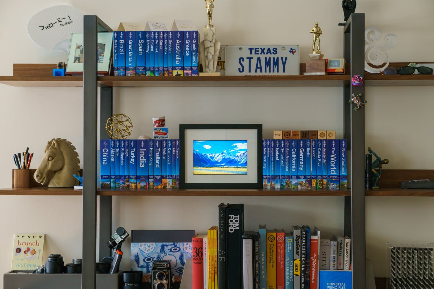
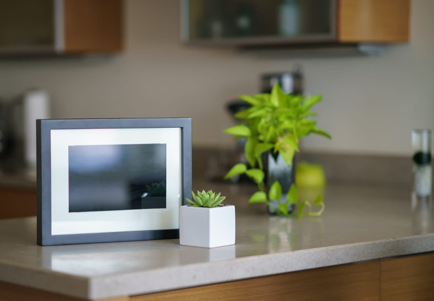
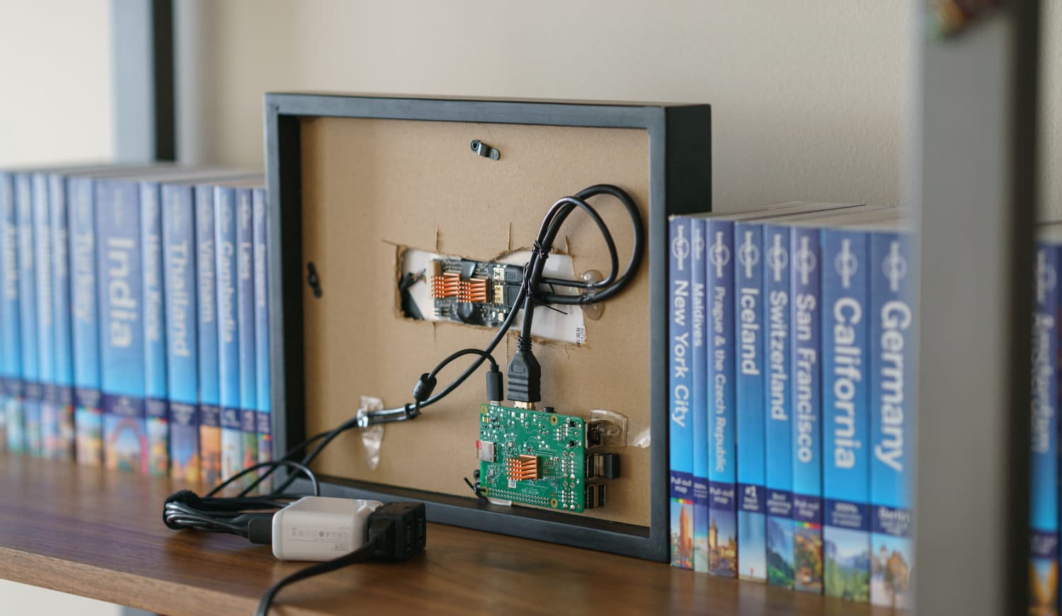
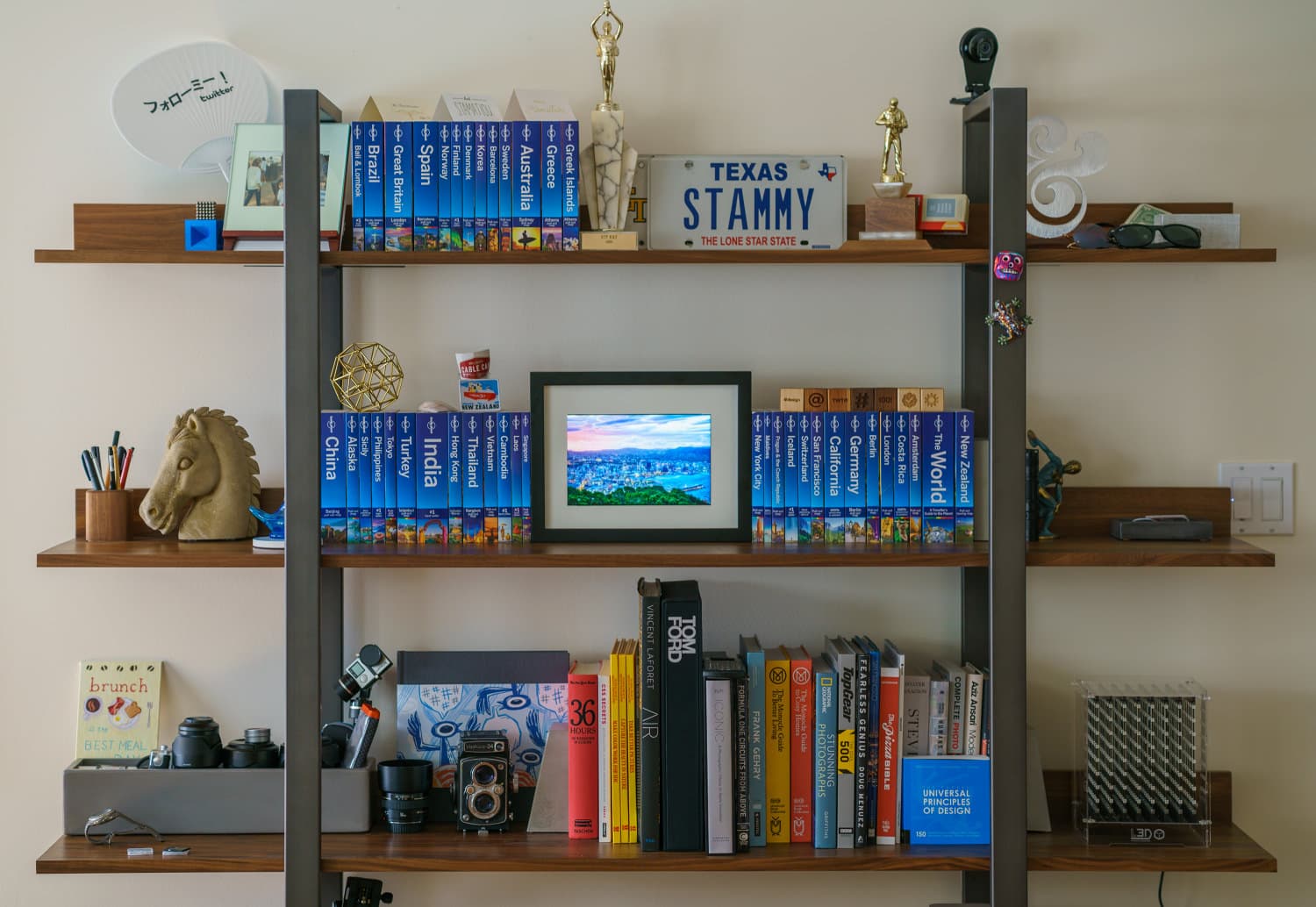
window.setInterval(function(){next_or_prev()}, interval * 1000);Now we're in business! With the photo display stuff figured out, I put the Pi Frame in its new home on my bookshelf. I nestled it in between my travel book collection, hooked up an extension cord to the Anker power adapter and hid the cable.
Turning the display off
With that out of the way, the next objective was to figure out how to turn off the display. There were two routes to explore. I could cut up the USB power cable going to the display and place a relay on it so the Pi's GPIO pin could programatically turn the power on and off. The other route would be to figure out how to programatically tell the display controller that there was no signal so it would turn off the backlight automatically. I explored the latter route.
I was unable to get the display and backlight to completely shutoff by simply setting the OS setting for display inactivity. It would black out the screen but the display controller would still think there was a video signal and keep the backlight on. What I needed to do was turn off the HDMI port entirely.
I wrote two bash scripts. The first, display_off.sh, simply ran this command: tvservice -o. I saved that file and made sure to chmod +x it to make it executable. I tested it out and it correctly turned off the display and backlight!
The next script to turn the display back on was a bit trickier. This is what I put in my display_on.sh script:
tvservice -p
chvt 9 && chvt 7
xrefresh -d :0
I tried a lot of stuff before I landed on something that worked. The chvt commands require sudo, so this script must always be run with sudo. I added the bash script to the sudoers file so that it at least doesn't ask for a password. I ran sudo visudo and added this line to the end (replace stammy with your Pi's username):
stammy ALL=NOPASSWD: /home/stammy/display_on.sh
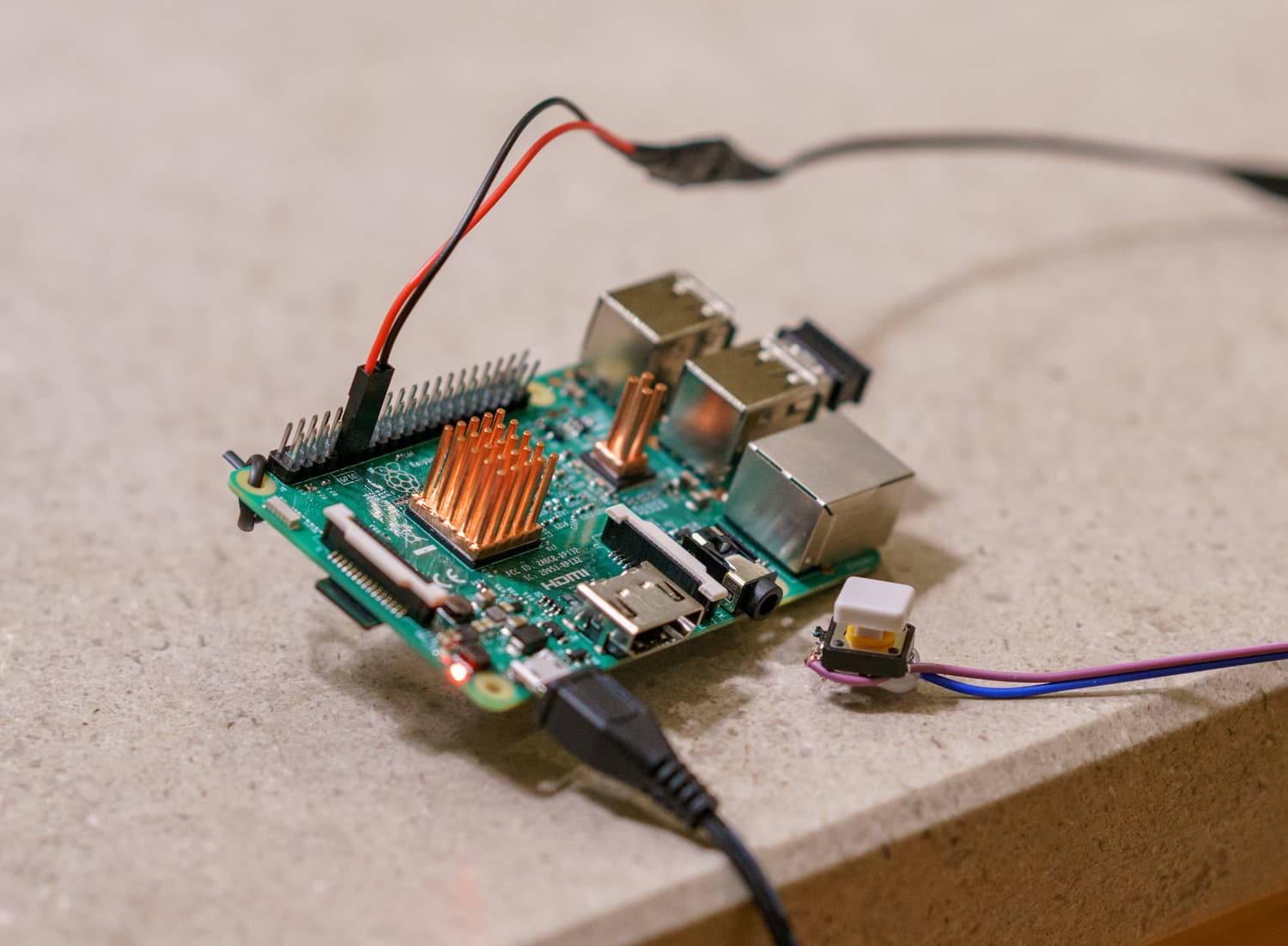
Wiring up a button and fan
With these two scripts I could SSH into the Pi and turn the display on and off. But SSHing into the Pi each time I wanted to toggle the display was going to be annoying. I decided to wire up a physical button to run this script for me. I soldered up a push button, hot glued it to the top right corner of the frame for easy access and attached it to GPIO pin 17 and GND.
But... if I was going to be doing a bit of soldering I figured I would also wire up a relay to control a fan to cool down the display controller board when running. It's probably not entirely necessary, but even with the copper heatsinks the display controller still gets very hot.
I rebuilt the relay circuit I talked about earlier in this article to control a small 5V 50mm fan powered off the Pi's 5V power source. Except this time I soldered everything (rather hackily at that) instead of using a breadboard. I wanted to use a transistor for this instead of a relay but I didn't have a 1N4001 flyback diode on hand to prevent inductive kickback when the fan shuts off.
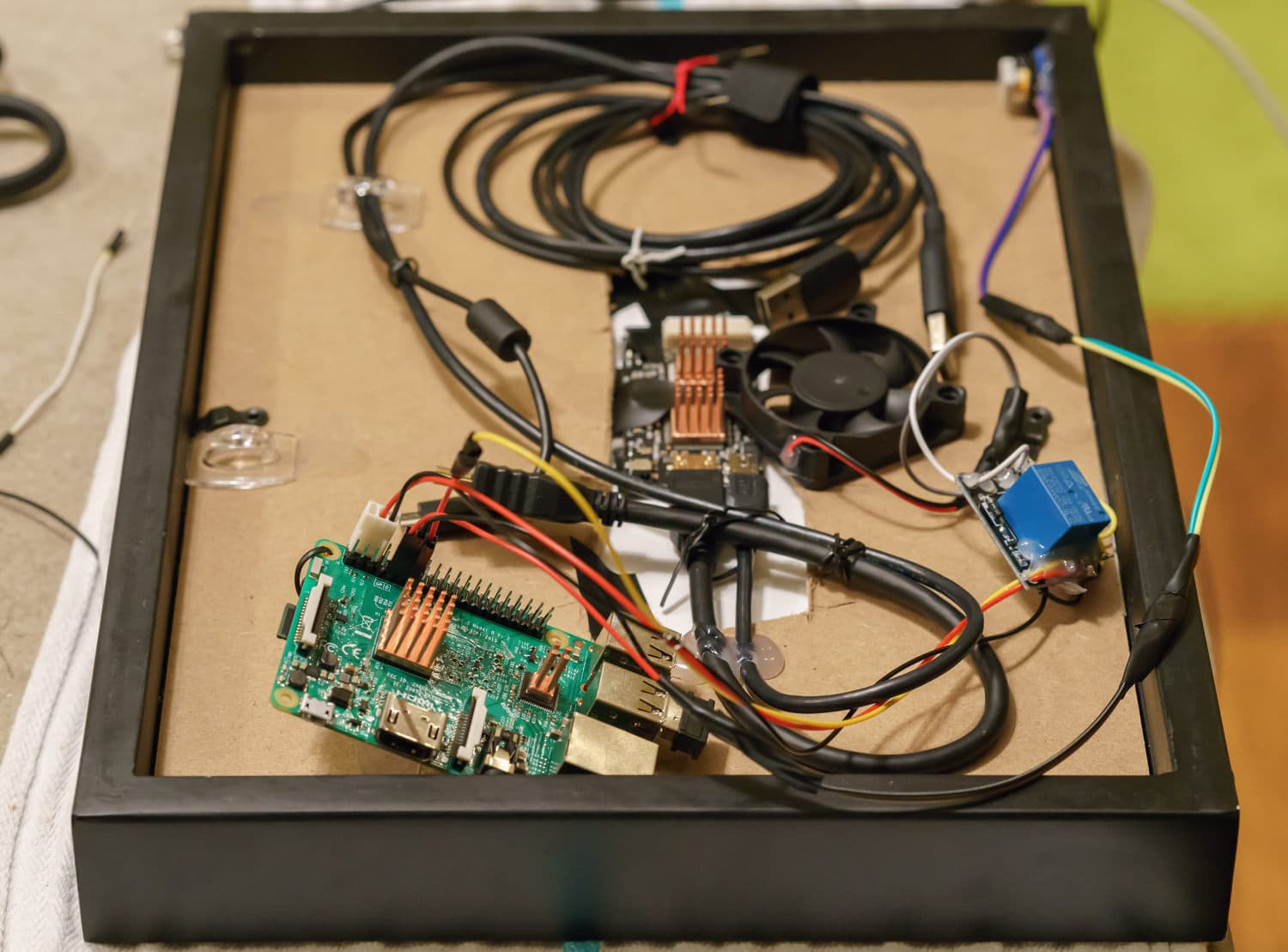
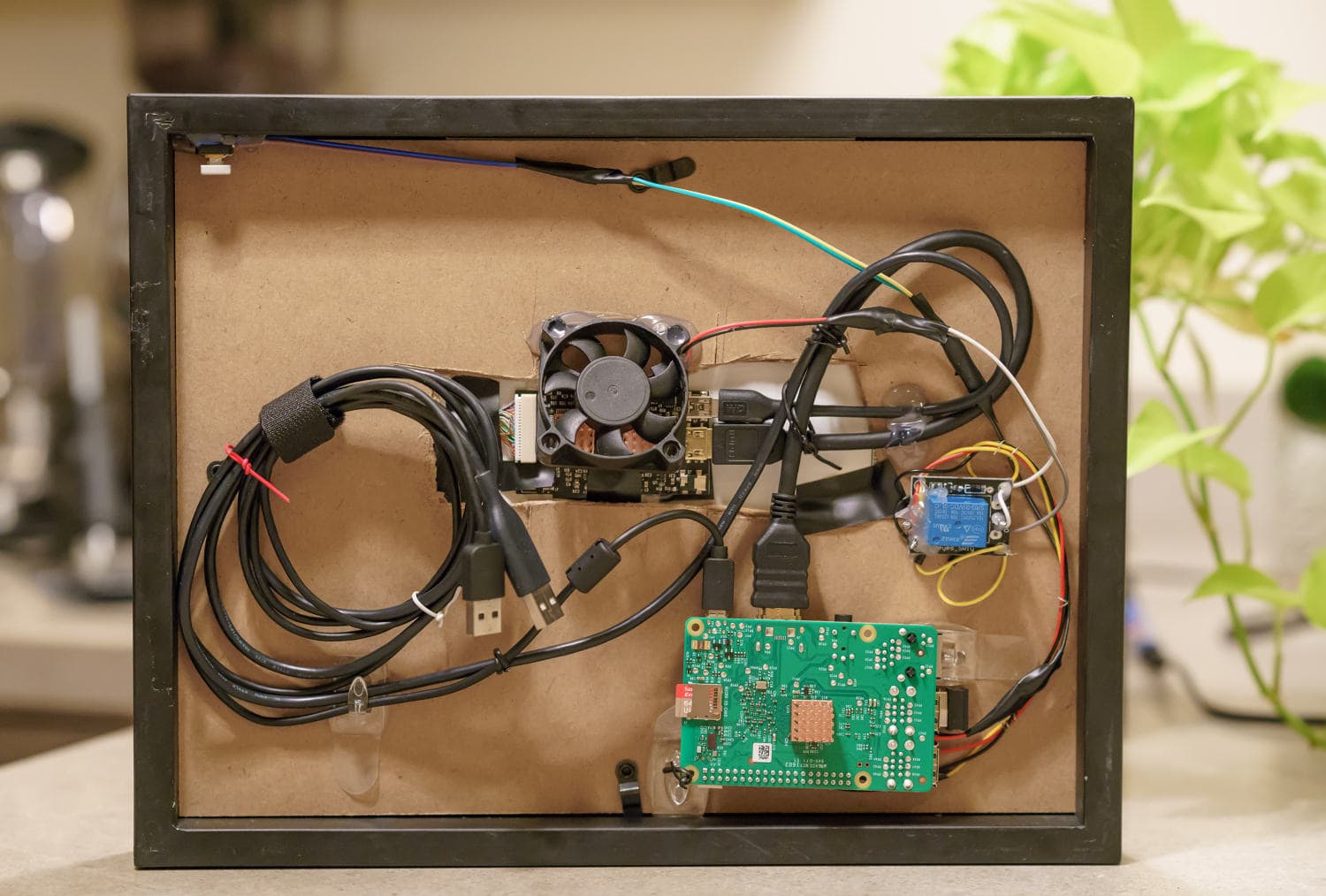
With everything back in place, I put the Pi Frame back on the bookshelf. I just had to write a python script to detect the button press then appropriately trigger the display on or off bash script and trigger the fan relay.
With the button hooked up to GPIO pin 17 I setup that pin to listen for input. One thing to note is that it is configured with the Pi's internal pull up resistor so I didn't have to use a resistor along with the button when wiring it up. This resistor configuration makes it easier for the Pi to distinguish if the button is being pushed by making it so that the pin's input voltage doesn't float (as it would with stray capacitance) when not connected to anything.
Since I just have the push button connected to GND and a GPIO pin, I use a pull-up resistor so the GPIO pin will read high normally and read low when the button is pushed. This is a bit opposite of what you may expect, thus why the script below only acts when the input is detected as false. The other way to do this is to wire the push button to a 3.3V line and a GPIO pin with a pull-down resistor. That will get the GPIO input to be pulled down to low by default and go high when the button is pressed and the circuit closes.
import RPi.GPIO as GPIO
import time
import subprocess

GPIO.setmode(GPIO.BCM)
GPIO.setup(17, GPIO.IN, pull_up_down=GPIO.PUD_UP)
GPIO.setup(27, GPIO.OUT, initial=GPIO.LOW)
display_on = True

while True:
    btn = GPIO.input(17)
    if btn == False:
        print('Button press registered')
        if display_on == True:
                display_on = False
                GPIO.output(27, False)
                subprocess.call("/home/stammy/display_off.sh", shell=True)
                time.sleep(0.5)
        elif display_on == False:
                display_on = True
                GPIO.output(27, True)
                subprocess.call("/home/stammy/display_on.sh", shell=True)
                time.sleep(0.5)
I connected the relay's signal line to GPIO pin 27 so I just needed to set that as output. Now I just listen for the button input and toggle between turning the display on and off. To actually run the aforementioned bash scripts I use the subprocess.call() lines. The time.sleep() lines are added in there so that holding the button a bit too long won't run the scripts multiple times.
I saved the script as a python file and ran it in a terminal on the Pi. Again, I need sudo here for the chvt commands mentioned above:
sudo python display_button.python
To make it easier whenever you reboot the Pi, you can add this as a custom application launcher in the top panel. Set it to Type: "Application in Terminal."
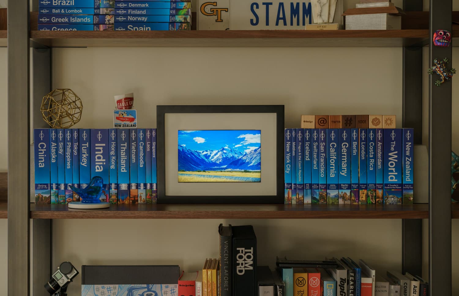
Time to actually enjoy the Pi Frame!
What's next with the Pi Frame?
I'm pretty impressed with the result of this little frame. Impressive, crisp image quality with a ridiculously easy Google Photos "integration"... love it. However, there are a few more things I'd like to explore with this project in the future:
- Get another matting sheet professionally cut to my exact spec since I was unable to replicate the same beveled cut it came with.
- Use a motion sensor to turn off the display after no movement has been detected in the room for a while.
- Replace Firefox with Chromium when the issues are addressed and see if I can get hardware accelerated videos working so that my videos on Google Photos can play well (they play now but frames drop). Detect proximity and if someone is actively looking at the display while a video is playing, enable audio to play through a small speaker.
- Setup an Amazon Echo Alexa skill so that I can tell the Pi to change to various Google Photos albums on command, or turn on/off the display.
- Connect a Leap Motion to be able to gesture between photos without needing to touch anything.
- Be able to use the display for various other tasks by hosting simple local webpages and changing the browser tab on command. For example one page could be a digital clock or analog clock with an interesting watch face.
Thanks for reading! If you've enjoyed this post I only ask that you please share it.
1 Which can only run older kernels and has worse software support.
2 Such as turning off unused ports, onboard LEDs and reducing on external accessories as well as excess software consuming CPU cycles. Here's an article that talks about doing this for the Pi Zero to reduce idle draw to a mere 80mA
3 There is actually a way to go through the initial setup via USB without a display at all, but it's a bit more complicated than I'd like to explain in this post. You can also preconfigure and build an image that has SSH ready to go so you can do the entire setup via SSH on boot, or if you use Raspbian it has SSH enabled by default. You'll need to connect via Ethernet instead of Wi-Fi at first and then follow these steps.
4 This actually installs an older version of netatalk, which still works but if you must always have the latest version of everything, search for how to setup netatalk 3.0+. You'll have to build it yourself, but it lets Spotlight index and search your Pi as well.
5 Though I think that is just 50mA across all GPIO pins combined. Not very much.
6 Especially if you will be using more than one GPIO pin since they seem to all share the 50mA maximum current available on the 3.3V line; though there is a chance this number is a bit higher for the Pi 3, it was very hard to actual find this listed anywhere official. What happens if you draw too much current off the GPIO pins when in output mode? Most likely it will just cause the Raspberry Pi to reboot. In more extreme scenarios of drawing lots of power (including various USB devices) you could blow the Raspberry Pi's built-in polyfuse which could take anywhere from a few minutes to hours to get back to normal.
7 Yeah, I'm still using the LED here to test it out but you can place a larger device here. Up to about ~500mA safely if you like, you just may want to power it from something other than the Pi's 5V line.
8 You'll have to do some searching for one that works at 3.3V, most require a bit more.. or just use a transistor to switch on that MOSFET with a larger power source.